K230 ISP Initial Setting#

Copyright 2023 Canaan Inc. ©
Disclaimer#
The products, services or features you purchase should be subject to Canaan Inc. (“Company”, hereinafter referred to as “Company”) and its affiliates are bound by the commercial contracts and terms and conditions of all or part of the products, services or features described in this document may not be covered by your purchase or use. Unless otherwise agreed in the contract, the Company does not provide any express or implied representations or warranties as to the correctness, reliability, completeness, merchantability, fitness for a particular purpose and non-infringement of any statements, information, or content in this document. Unless otherwise agreed, this document is intended as a guide for use only.
Due to product version upgrades or other reasons, the content of this document may be updated or modified from time to time without any notice.
Trademark Notice#
![]() , “Canaan” and other Canaan trademarks are trademarks of Canaan Inc. and its affiliates. All other trademarks or registered trademarks that may be mentioned in this document are owned by their respective owners.
, “Canaan” and other Canaan trademarks are trademarks of Canaan Inc. and its affiliates. All other trademarks or registered trademarks that may be mentioned in this document are owned by their respective owners.
Copyright 2023 Canaan Inc. © All Rights Reserved. Without the written permission of the company, no unit or individual may extract or copy part or all of the content of this document without authorization, and shall not disseminate it in any form.
Directory#
[TOC]
Preface#
Overview#
This document mainly guides users to set the initialization for K230 ISP.
Reader object#
This document (this guide) is intended primarily for:
Image Tuning Engineer
Technical Support Engineer
Software Development Engineer
Revision history#
Document version number |
Modify the description |
Author |
date |
|---|---|---|---|
V1.0 |
Initial edition |
Rong Jian |
2024-01-24 |
V1.1 |
Updated some parameters descriptions |
Rong Jian |
2024-04-28 |
1. K230 ISP Initial Setting Overview#
After image tuning, the ISP configuration parameters formed need to be written into the initialization configuration files of the corresponding sensor. When K230 turned on, the ISP will automatically load the initial settings from these configuration files. When an adaptive function is enabled, the ISP will operate according to the adaptive settings of this function.
The ISP initialization configuration include three files: an xml file, a manual.json file, and an auto.json file. If sensor settings have several resolutions to be selected, these three configuration files are required for each resolution.
These configuration files are stored in followling directiory: \ k230_ In the sdk \ src \ big \ mpp \ userapps \ src \ sensor \ config.
2. xml file#
2.1 Overview#
The K230 ISP Calibration Tool (K230ISPCalibrationTool.exe) can be used to generate XML files, and the calibration for all modules in the Calibration Tool must be completed to obtain complete calibration data.
Calibration parameters are generated in two ways:
The calibration reslut from the Calibration Tools
The professional data files provided in the release package
The storage locations of calibration data and calibration parameter files are shown in the table below.
Calibration Data |
Generation Method or Parameter File |
Calibration Parameter File Location |
|---|---|---|
Auto White Balance |
Calibration Tool |
sensor/lens/sample/AWB/ |
Black Level Calibration |
Calibration Tool |
sensor/lens/sample/BlackLevel/ |
Chromatic Aberration |
Calibration Tool |
sensor/lens/sample/Calibration Tool/ChromaticAberration/ |
Color Calibration |
Calibration Tool |
sensor/lens/sample/Calibration Tool/ColorReproduction/ |
Defect Pixel Color Correction |
dpcc_para.txt |
sensor/lens/sample/Calibration Tool/DefectPixel/ |
Auto Exposure Calibration |
aec_para.m; k_para.txt |
sensor/lens/sample/Calibration Tool/ExposureCalibration/ |
HDR |
hdr_para.txt |
sensor/lens/sample/Calibration Tool/HDR/ |
Lens Shading Correction |
Calibration Tool |
sensor/lens/sample/Calibration Tool/LensShading/ |
Noise Calibration |
Calibration Tool |
sensor/lens/sample/Calibration Tool/Noise/ |
Photo Response Linearity |
degamma_para.txt |
sensor/lens/sample/Calibration Tool/PhotoResponseLinearity/ |
2.2 Setup Calibration File Folders with Calibration Parameters#
Please create folders for each resolution as the following steps:
Create a folder using the sensor name (e.g., /OV9732)
Create a sub-folder with the lens name (e.g., /2MP)
Create a sub-folder with the sample name (e.g., /01_30)
Create sub-folders for each of the calibration function (As shown in the following figure)
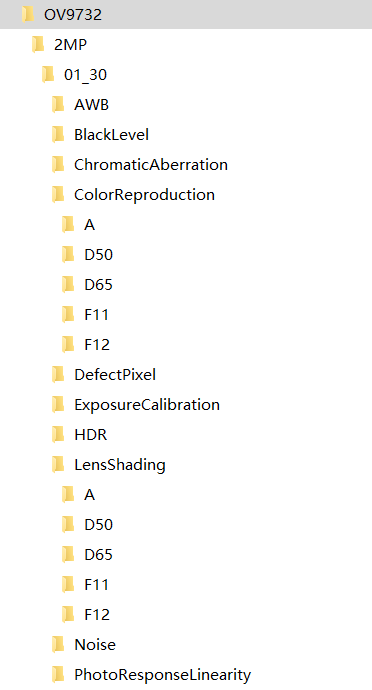
Copy calibration parameter file(s) into the corresponding parameter folder.
For example, for each resolution:
sensor
lens
sample
AWB
AWB parameters.txt
AWB parameters.mat
BlackLevel
BLS parameters.txt
…
2.3 Generate XML file using K230 ISP Calibration Tool#
After copying all calibration parameter files to the corresponding folder, open the K230 ISP Calibration Tool and use it to generate an XML file.
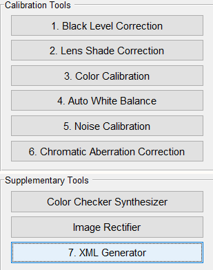
As shown in the following figure, click the “7. XML Generator” button on the main interface:
Pop up the “XML Generator” box as below:
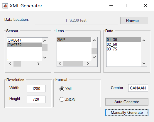
Select the correct calibration directory address in the “Data Location” column, select the created sensor folder in the “Sensor” column, select the created lens folder in the “Lens” selection column, and select the created sample folder in the “Data” column.
In the “Resolution” column, input the correct width and height of the image, select “XML” in the “Format” column, input the creator name in the “Creator” column, and then click “Manually Generate” to generate an “XML” subdirectory under the selected lens folder, which will generate an .xml file.
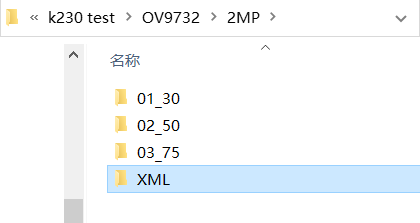
After renaming the generated XML file according to the input XML name in the K230 SDK (such as ov9732-1280x720.xml) code, place it in the config directory and it will be loaded correctly by the K230 SDK.
2.4 AWB parameter K_Factor#
In the awb sub section of the XML file, there is a K_Factor parameter that needs to be calibrated and manually filled in separately. This parameter provides feedback on the sensitivity of the camera module.
In the AWB algorithm, the judgement for outdoor environment is: Exp*K_Factor <=0.12 (Exp is exposure).
For example, take 2000 lux as the ambient illumination segmentation point for the outdoor and transition, obtain the exposure value (ET * gain) corresponding to this illumination and calculate: K_Factor=0.12/(ET * gain).
3. manual.json file#
The manual.json file needs to be manually created. Please refer to imx335-2592x1944_manual.json to create a *_manual.json file for the required sensor resolution.
3.1 CHdrv2#
3.1.1 Function Description#
This module is for setting HDR mode parameters that are not included in other ISP modules.
3.1.2 Main Parameters#
parameter |
Type and value range |
description |
|---|---|---|
base_frame |
int 0~1 |
0: base on S frame; |
bls_out |
int[4] |
Black level out <br/Default setting is [0,0,0,0],value based on ISP 12bits. |
bypass |
bool |
false: HDR enable |
bypass_select |
int 0~2 |
0: HDR output long frame; |
color_weight |
int[3] 0~255 |
color_weight |
driver_load |
bool |
false: don’t load this class |
enable |
bool |
false: HDR disable |
extend_bit |
int[2] -1~8 |
extend bit |
ratio |
float[3] 1.0~256.0 |
Exposure ratio |
sensor_type |
int 0~6 |
0,1,2: L_12+S_12+VS_12 |
stitching_mode |
int 0~1 |
0: linear stitching mode; |
trans_range |
float[6][2] 0.0~1.0 |
Start and end values of merge range |
In the above table:
Frame |
description |
|---|---|
L |
(exposure) long frame |
S |
(exposure) short frame |
VS |
(exposure) very short frame |
LS |
L & S merged frame |
LSVS |
LS & VS merged frame |
Please note: in K230 HDR mode, the K230 CSI (Camera serial interface) module does not support the sensor data mode of Hsync before Vsync. And when the Vsync of each frame (L/S/VS) is high (effective data output), there should be no overlap.
3.2 CGreenEqu#
Please refer to Chapter 3.7 of the 《K230 ISP Image Tuning Guide》.
3.3 CRgbIR#
3.3.1 Function Description#
This module is for setting RGBIR pattern.
3.3.2 Main Parameters#
parameter |
Type and value range |
description |
|---|---|---|
bit |
int |
12, fixed value |
ccmatrix |
float[12] |
3x4 color conversion matrix, convert RGBIR value to RGB value |
dpcc_mid_th |
int |
DPCC median threshold of channel |
dpcc_th |
int |
DPCC threshold of channel |
enable |
bool |
false: RGBIR sub-module disable |
gain |
int[3] |
Gain value for R/G/B chaneels |
ir_threshold |
int |
IR high threshold |
irbayer_pattern |
int |
RGBIR pattern type |
l_threshold |
int |
IR low threshold |
out_rgb_pattern |
int |
output RGB data pattern |
3.4 CManualWb#
Please refer to Chapter 3.12 of the 《K230 ISP Image Tuning Guide》.
3.5 CCcm#
Please refer to Chapter 3.13 of the 《K230 ISP Image Tuning Guide》.
3.6 CDgain#
Please refer to Chapter 3.3 of the 《K230 ISP Image Tuning Guide》.
3.7 CCpdv1#
Please refer to Chapter 3.19 of the 《K230 ISP Image Tuning Guide》.
3.8 Bls#
3.8.1 Function Description#
This module is for setting black level. The default setting of Bls module enable is enabled.
3.8.2 Main Parameters#
parameter |
Type and value range |
description |
|---|---|---|
bls |
int[4] |
Black level |
3.9 CGamma64#
Please refer to Chapter 3.14 of the 《K230 ISP Image Tuning Guide》.
3.10 CDpcc#
Please refer to Chapter 3.8 of the 《K230 SP Image Tuning Guide》.
3.11 CDpf#
Please refer to Chapter 3.9 of the 《K230 ISP Image Tuning Guide》.
3.12 CLscv2#
Please refer to Chapter 3.2 of the 《K230 ISP Image Tuning Guide》.
3.13 CWdrv4#
Please refer to Chapter 3.6 of the 《K230 ISP Image Tuning Guide》.
3.14 C3dnrv3_1#
Please refer to Chapter 3.10 of the 《K230 ISP Image Tuning Guide》.
3.15 CCproc#
Please refer to Chapter 3.18 of the 《K230_SP_Image Tuning Guide》.
3.16 CEEv1#
3.16.1 Function Description#
This module includes three sub-modules: CA, DCI and EE .
3.16.2 Main Parameters#
Please refer to the Chapter 3.15(EE), 3.16(CA) and 3.17(DCI) of the 《K230 ISP Image Tuning Guide》.
3.17 CDmscv2#
3.17.1 Function Description#
This module includes two sub-modules: CAC and DSMC.
3.17.2 Main Parameters#
Please refer to Chapter 3.20 of the 《K230 ISP Image Tuning Guide》 for CAC parameter settings.
And please refer to Chapter 3.11 of the 《K230 ISP Image Tuning Guide》 for DSMC parameter settings.
4. auto.json file#
The auto.json file needs to be manually created. Please refer to imx335-2592x1944_auto.json to create a *_auto.json file for the required sensor resolution.
4.1 AdaptiveAe#
4.1.1 Function Description#
This module is used to set the parameters for the AE control and AE adaptive function.
4.1.2 Main parameters#
parameter |
Type and value range |
description |
|---|---|---|
enable |
bool |
false: disable AE |
semMode |
int 0~2 |
Scene mode |
antiFlickerMode |
Int 0~3 |
Anti-Banding working mode |
setPoint |
float 0~255.0 |
Set the target brightness value for AE |
tolerance |
float 0~100.0 |
Set the percentage lock range of AE’s brightness target value |
dampOver |
float 0~1.0 |
Damping factor to smooth AE convergence during overexposure |
dampOverGain |
float 0~128.0 |
The convergence acceleration gain factor outside the clip range when AE is overexposed. If the value is larger, the convergence will be faster. |
dampOverRatio |
float 1.0~4.0 |
The scale factor outside the clip range when AE is overexposed. If the value is smaller, the convergence will be faster. |
dampUnder |
float 0~1.0 |
Damping factor to smooth AE convergence under exposure |
dampUnderGain |
float 0~16.0 |
The convergence acceleration gain factor outside the clip range when AE is underexposed. If the value is larger, the convergence will be faster. |
dampUnderRatio |
float 0~1.0 |
The clip range scale factor when AE is underexposed. If the value is larger, the convergence will be faster. |
motionFilter |
float 0~1.0 |
Motion filter, use to calculate the motion factor at AE scene evaluation adaptive mode |
motionThreshold |
float 0~1.0 |
Motion threshold |
targetFilter |
float 0~1.0 |
The smoothness coefficient for the AE setpoint value change, with larger values leading to faster changes |
lowLightLinearRepress |
float[20] 0~1.0 |
The repress ratios of each “gain” levels at linear mode |
lowLightLinearGain |
float[20] 0~255.0 |
The gain values of each “gain” levels at linear mode, the maximum “gain” level is 20. |
lowLightLinearLevel |
int 0~19 |
total gain levels at linear mode |
lowLightHdrRepress |
float[20] 0~1.0 |
The repress ratios of each “gain” levels at HDR mode |
lowLightHdrGain |
float[20] 0~255.0 |
The gain values of each “gain” levels at HDR mode, the maximum “gain” level is 20. |
lowLightHdrLevel |
int 0~16 |
total gain levels at HDR mode |
wdrContrastMax |
float 0~255.0 |
Maximum contrast value for calcuating AE setpoint at AE scene evaluation adaptive mode |
wdrContrastMin |
float 0~255.0 |
Minimum contrast value for calcuating AE setpoint at AE scene evaluation adaptive mode |
frameCalEnable |
bool |
Exposure setting frame interval enable switch |
autoHdrEnable |
bool |
true: auto calculate the HDR ratio at HDR mode |
roiNumber |
int |
the seiral number of current ROI window |
roiWindow |
float (fx,fy,fw,fh,weight) |
the starting point coordinates (x, y), width&height abd weight of the current ROI window |
expV2WindowWeight |
float[32x32] 0~255 |
the exposure weight for every grid |
4.2 Awbv2#
4.2.1 Function Description#
This module is used to set the parameters for the awb adaptive function. It has not yet taken effect.
4.2.2 Main Parameters#
parameter |
Type and value range |
description |
|---|---|---|
enable |
bool |
false: disable AWB |
mode |
int 0,1 |
0: AWB |
useCcMatrix |
bool |
false: disable CCM adaptive |
useCcOffset |
bool |
false: disable CCM offset adaptive |
useDamping |
bool |
false: disable AWB damping |
roiNumber |
int |
The serial number of current ROI window |
roiWindow |
float (fx,fy,fw,fh,weight) |
Current ROI window’s starting coordinate(x,y), width, height and AWB weight |
4.3 Af#
4.3.1 Function Description#
This module is used to set the parameters for the AF function. It has not yet taken effect.
4.3.2 Main Parameters#
parameter |
Type and value range |
description |
|---|---|---|
enable |
bool |
false: disable AF |
mode |
int |
0: normal AF mode |
weightWindow |
float[3] 0~255.0 |
Set the weight values of three statistical value windows for sharpness calculation. |
cMotionThreshold |
float 0~1.0 |
Not used yet, will be used for motion detection. |
cPointsOfCurve |
int 1~20 |
The number of equal parts in the AF climbing algorithm. If the value is larger, the focusing speed is slower; If the value is small, the focusing speed is faster, but excessive movement step size can cause some degree of inaccurate focusing. |
cStableTolerance |
float 0~1.0 |
The threshold for AF to enter defocus state from locked state. If the value is smaller, it is more likely to lose focus and enter a refocusing state. |
focalFilter |
float[5] 0~1023 |
Not yet used |
shapFilter |
float[5] 0~1023 |
Not yet used |
focalStableThreshold |
float 0~1.0 |
The threshold for the focus locked state. If the value is smaller, it becomes more difficult to enter the locked state. |
maxFocal |
int 0~1023 |
Maximum motor position |
minFocal |
int 0~1023 |
Minimum motor position |
cMseTolerance |
float 0~1.0 |
Not yet used |
cPdConfThreshold |
float 0~1023.0 |
Not used |
PdFocal |
int -254~254 |
Not used |
PdDistance |
int 1~254 |
Not used |
PdShiftThrehold |
float 0~1.0 |
Not used |
PdStablecountMax |
uint8 1~10 |
Not used |
PdROIIndex |
uint8 0~48 |
Not used |
4.4 ALscv2#
4.4.1 Function Description#
This module is used to set the parameters for LSC adaptive function.
4.4.2 Main Parameters#
parameter |
Type and value range |
description |
|---|---|---|
enable |
bool |
false: disable ALSC |
damping |
float |
damping factor to smooth LSC curve changes during ALSC |
interMode |
int 0~2 |
0: Adaptive adjustment based on gain value |
hdr |
bool |
false: means that the group is set for linear mode |
gain |
float[20] |
gain values of each level |
strength |
float[20] 0~1.0 |
the strength of the retained LSC based on the gain values of each level |
4.5 Others#
This chapter introduces other adaptive function modules.
The parameters of these adaptive function modules are usually divided into two parts by “tables” and the following brackets “[]”. The parameters outside the brackets “[]” are bool type parameters, and the parameters inside the brackets “[]” are parameters that participate in adaptive function adjustment.
4.5.1 Parameters description outside of “tables”#
In these adaptive functional modules, there are usually three parameters outside of “tables”:
parameter |
Type |
description |
|---|---|---|
disable |
bool |
please set to false |
enable |
bool |
false: disable; true: enable |
forcecreate |
bool |
please set to true |
In the A3dnrv3 module, there are two additional parameters outside of “table”:
parameter |
Type |
description |
|---|---|---|
nlm_en |
bool |
NLM (Non-local Means) denoise enable switch. |
tnr_en |
bool |
TNR (temporal noise reduction) enable switch. |
4.5.2 Parameters description in “tables”#
In adaptive function modules, there are two parameters:
parameter |
Type |
description |
|---|---|---|
hdr |
bool |
false: means that the group is set for linear mode |
gain |
float[20] |
Gain values of each level |
For other adaptive parameters, please refer to the corresponding function chapters in the《 K230 ISP Image Tuning Guide》.
“Gain” can be divided into up to 20 levels from the minimum value (usually 1 times) to the maximum value, and each level requires the corresponding gain value to be set in the gain parameter array.
Please note that each adaptive module can customize different levels according to its adaptive needs, with a maximum of 20 levels.
All adaptive parameters in the same adaptive fucntion module have the same number of levels as “gain”, and each level should be set with appropriate values based on the corresponding gain value of the same level.