K230 SDK CanMV Board Demo User Guide#

Copyright©2023 Beijing Canaan Creative Information Technology Co., Ltd.
Disclaimer#
The products, services, or features you purchase are subject to the commercial contracts and terms of Beijing Canaan Creative Information Technology Co., Ltd. (“the Company”, hereinafter the same) and its affiliates. All or part of the products, services, or features described in this document may not be within the scope of your purchase or use. Unless otherwise agreed in the contract, the Company does not provide any express or implied statements or warranties regarding the correctness, reliability, completeness, merchantability, fitness for a particular purpose, and non-infringement of any statements, information, or content in this document. Unless otherwise agreed, this document is for reference only.
Due to product version upgrades or other reasons, the content of this document may be updated or modified periodically without any notice.
Trademark Statement#
![]() , “Canaan”, and other Canaan trademarks are trademarks of Beijing Canaan Creative Information Technology Co., Ltd. and its affiliates. All other trademarks or registered trademarks mentioned in this document are owned by their respective owners.
, “Canaan”, and other Canaan trademarks are trademarks of Beijing Canaan Creative Information Technology Co., Ltd. and its affiliates. All other trademarks or registered trademarks mentioned in this document are owned by their respective owners.
Copyright © 2023 Beijing Canaan Creative Information Technology Co., Ltd. All rights reserved. Without the written permission of the Company, no unit or individual may excerpt, copy any part or all of the contents of this document, nor disseminate it in any form.
Table of Contents#
[TOC]
Preface#
Overview#
This document mainly introduces the demo programs provided in the K230 SDK adapted to the Canmv-K230 development board.
Intended Audience#
This document (this guide) is mainly intended for the following personnel:
Technical Support Engineers
Software Development Engineers
Abbreviation Definitions#
Abbreviation |
Description |
|---|---|
UVC |
USB video class (USB camera) |
VVI |
Virtual video input, mainly used for pipeline debugging |
Revision History#
Document Version |
Description |
Editor |
Date |
|---|---|---|---|
V1.0 |
Initial Version |
System Software Department |
2023-10-11 |
1. Overview#
This document introduces the demo functions provided by the K230 SDK and their usage. The executable programs on rt-smart are all compiled by default into the small core/sharefs directory. When testing the large core programs, you need to wait for the small core to fully start, and then enter the /sharefs/app directory in the large core’s msh to test. The audio and video resource files used in each test demo can be obtained from the following link: https://kendryte-download.canaan-creative.com/k230/downloads/test_resource/
2. Demo Introduction#
2.1 Display_demo#
2.1.1 Display_demo Introduction#
The VO (Video Output) module actively reads video and graphic data from the corresponding memory location and outputs video and graphics through the corresponding display device. It supports display/write-back devices, video layers, and graphic layers.
2.1.2 Feature Description#
Video output includes a test case, which is the insertion of frames into the vo osd layer.
2.1.3 Dependency Resources#
A monitor with an HDMI interface and an HDMI cable. The monitor must support 1080P30, otherwise, it will not display.
2.1.4 Usage Instructions#
2.1.4.1 Compilation#
Refer to the README.md in the release SDK software package for software compilation.
2.1.4.2 Execution#
Insert a frame into the vo osd layer:
./sample_vo.elf 15
After executing the command, pressing Enter once will insert a pure green image, pressing Enter again will exit the program.
The display effect is as follows:

2.2 Venc_demo#
2.2.1 Venc_demo Introduction#
The Venc demo encodes the graphics received by vi and can add a frame and OSD overlay to the input image. It supports encoding protocols H.264/H.265/JPEG. The encoded result can be stored as a file and exported locally for playback using video software.
2.2.2 Feature Description#
Only supports 1280x720 resolution.
2.2.3 Dependency Resources#
Camera
2.2.4 Usage Instructions#
2.2.4.1 mpp_demo Execution#
After executing ./sample_venc.elf -h, the usage instructions for the demo are output as follows:
Usage : ./sample_venc.elf [index] -sensor [sensor_index] -o [filename]
index:
    0) H.265e.
    1) JPEG encode.
    2) OSD + H.264e.
    3) OSD + Border + H.265e.

sensor_index: see vicap doc
Refer to the k230_docs/zh/01_software/board/mpp/K230_Camera_Sensor适配指南.md document for the sensor_index values regarding k_vicap_sensor_type, the default value is 7.
Example:
./sample_venc.elf 0 -sensor 24 -o out.265 // Canmv-K230-V1.0/1.1 board
./sample_venc.elf 0 -sensor 39 -o out.265 // Canmv-K230-V2.0 board
2.2.4.2 MAPI Encoding Demo#
The default sensor type used by sample_venc is IMX335_MIPI_2LANE_RAW12_1920X1080_30FPS_LINEAR. Currently, this demo supports 3 channels of encoding. The sensor type and other parameters can be modified through command line arguments as described below:
After starting the development board:
Use
lsmodto check if the k_ipcm module is loaded on the small core side. If not, executeinsmod k_ipcm.koto load the k_ipcm module.Start the inter-core communication process on the large core side by executing
./sample_sys_init.elf.On the small core side, in the /mnt directory, execute
./sample_venc. By default, it performs one channel of h264 video encoding with a resolution of 1280x720, and the generated stream file is stored in the /tmp directory. To pass parameters, refer to the following parameter description:
Usage: ./sample_venc -s 24 -n 2 -o /tmp -t 0            // Canmv-K230-V1.0/1.1 board
                     -s or --sensor_type [sensor_index],\n");
                            see vicap doc
                     -n or --chn_num [number], 1, 2, 3
                     -t or --type [type_index]
                            0: h264 type
                            1: h265 type
                            2: jpeg type
                     -o or --out_path [output_path]
                     -h or --help, will print usage

Usage: ./sample_venc -s 39 -n 2 -o /tmp -t 0            // Canmv-K230-V2.0 board
Refer to the k230_docs/zh/01_software/board/mpp/K230_Camera_Sensor适配指南.md document for the sensor_index values regarding k_vicap_sensor_type, the default value is 7.
You can stop the execution by pressing ctrl+c. Depending on the encoding type, different stream files will be generated in the specified output directory on the small core. For h264 type, files like stream_chn0.264 will be generated, where 0 represents channel 0; for h265 type, files like stream_chn0.265 will be generated, similarly, 0 represents channel 0; for jpeg type, files like chn0_0.jpg will be generated, representing the 0th image of channel 0, and by default, 10 jpg images will be generated.
2.2.4.3 Viewing Results#
The output file can be exported locally and viewed using video playback software.
2.3 Nonai_2d_demo#
2.3.1 Nonai_2d_demo Introduction#
The Nonai_2d demo implements image overlay functions on the input file.
2.3.2 Feature Description#
Nonai_2d performs image overlay operations by reading yuv (I420 format) files.
2.3.3 Dependency Resources#
None.
2.3.4 Usage Instructions#
The input parameters are as follows:
Parameter Name |
Description |
Default Value |
|---|---|---|
-i |
Input file name |
- |
-w |
Image width |
- |
-h |
Image height |
- |
-o |
Output file name |
- |
2.3.4.1 Execution#
Example:
./sample_nonai_2d.elf -i /sharefs/foreman_128x64_3frames.yuv -w 128 -h 64 -o /sharefs/out_2d.yuv
2.3.4.2 Viewing Results#
The output file can be exported locally and viewed using yuv playback software.
2.4 Vdec_demo#
2.4.1 Vdec_demo Introduction#
The Vdec demo implements video decoding functions. It supports decoding H.264/H.265/JPEG formats. The supported input data formats are .264/.265/.jpeg.
2.4.2 Feature Description#
The Vdec demo decodes by reading stream files. The decoding output results are displayed on the screen.
2.4.3 Dependency Resources#
None.
2.4.4 Usage Instructions#
2.4.4.1 Execution#
Execute ./sample_vdec.elf -help to see the configurable parameters and descriptions. The default values are as follows:
Parameter Name |
Description |
Default Value |
|---|---|---|
i |
Input file name, with suffixes .264/.265/.jpg |
- |
type |
vo connector type, refer to the vo documentation |
0 |
The type values refer to the description of k_connector_type in k230_docs/zh/01_software/board/mpp/K230_视频输出_API参考.md, set to 0.
2.4.4.1.1 VDEC Binding VO Decoding Display#
./sample_vdec.elf -type 1 -i canaan.264
2.4.4.1.2 MAPI VDEC Binding VO Decoding Display#
./sample_vdec.elf -type 1 -i canaan.264
2.4.4.2 Viewing Results#
The decoding results can be viewed on the screen.
2.5 Audio_demo#
2.5.1 Audio_demo Introduction#
The audio demo implements audio input and output functions by calling API interfaces. Both audio input and output use the i2s module. The demo includes test cases for audio input or output individually, as well as simultaneous testing of audio input and output.
2.5.2 Feature Description#
2.5.2.1 Audio Input#
Audio input captures the sound from the environment and saves it as a file to analyze whether it is normal.
The demo captures 15 seconds of audio data, and the captured file format is wav, which can be directly played using VLC.
2.5.2.2 Audio Output#
Audio output plays wav files, and by plugging in earphones, you can judge whether the sound is normal.
The demo tests the audio output function by playing wav files. Different audio format wav files can be uploaded to test the audio output function.
2.5.2.3 Audio Input and Output#
Audio input and output can be tested simultaneously.
Test the i2s module function, i.e., real-time capture of environmental sounds through i2s audio input and real-time output through i2s audio output. By plugging in earphones, you can hear the environmental sounds in real-time.
2.5.2.4 Audio Encoding and Decoding#
Built-in g711a/u 16bit audio codec, users can register other external codecs.
2.5.3 Usage Instructions#
2.5.3.1 Compilation#
Refer to the
README.mdin the SDK for the software compilation environment.
2.5.3.2 Execution#
After entering the rt-smart system, go to the /sharefs/app directory, sample_audio.elf is the test demo.
You can input
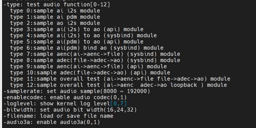
./sample_audio.elf -helpto see the usage of the demo.Use the
-typeoption to test different module functions;Use the
-samplerateoption to configure different sampling rates for audio input and output (8k-192k), the default is 44.1k;Use the
-enablecodecoption to use the built-in codec or external audio sub-board;Use the
-logleveloption to print the kernel log level;Use the
-bitwidthoption to set the audio sampling precision (16/24/32);Use the
-filenameoption to load or store wav/g711 file names.
2.5.3.2.1 I2S Audio Input Test#
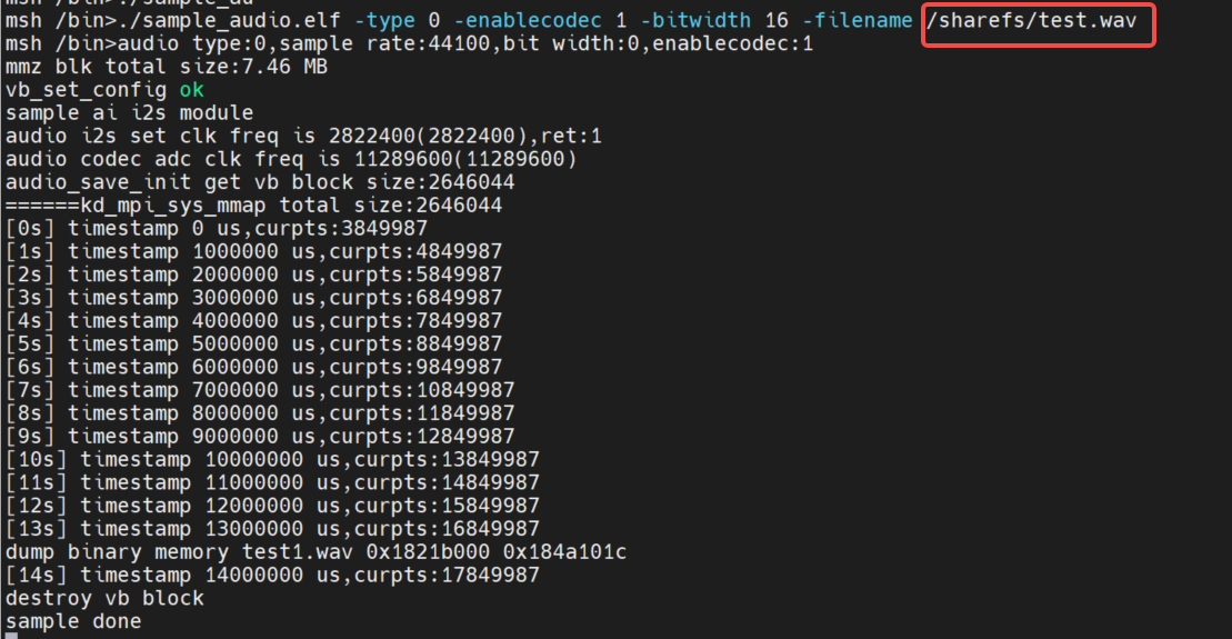
Input
./sample_audio.elf -type 0to capture 15 seconds of pcm audio data,Use the
-samplerateoption to select different sampling rates for capturing audio,Use the
-bitwidthoption to set different sampling precision,Use the
-enablecodecoption to set whether to use the built-in codec,Use the
-filenameoption to save data to a file. After capturing 15 seconds of data, the demo will automatically exit.
Demo implementation idea: This test captures data by calling the API functions kd_mpi_ai_get_frame and kd_mpi_ai_release_frame in a loop. Note that the ai dev number corresponding to i2s is 0.
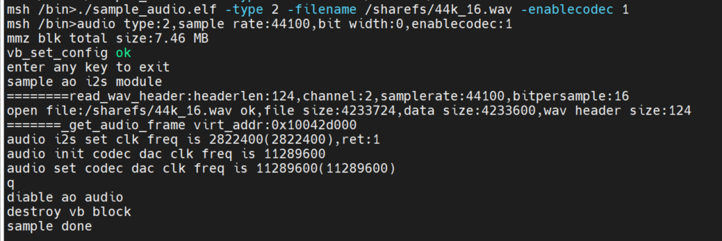
2.5.3.2.2 I2S Audio Output Test#
Supports playing wav files, the wav file needs to be copied to the sharefs path. This demo will loop playback the wav file (other arbitrary wav files can also be used), and users can press any key to exit this function test.
Demo implementation idea: This test outputs sound in real-time by calling the API function kd_mpi_ao_send_frame in a loop.
2.5.3.2.3 I2S Audio Input and Output API Interface Test#
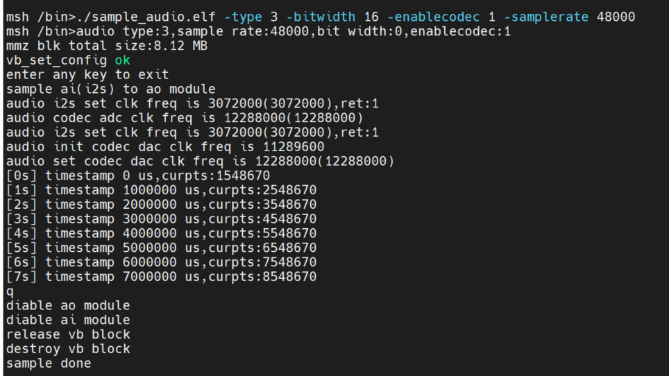
Input ./sample_audio.elf -type 3 -bitwidth 16 to test the real-time audio input and output functions through the API interface.
By calling the API interface: kd_mpi_ai_get_frame to obtain audio data and kd_mpi_ao_send_frame to output audio data, the overall functionality of audio input and output can be tested. The user can press any key to exit this function test. During the test, the timestamp information collected by the AI will be output in real-time.
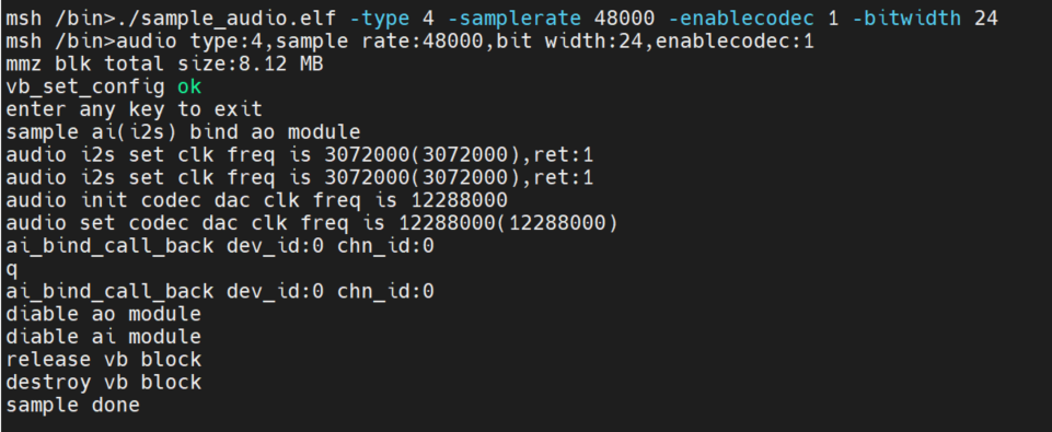
2.5.3.2.4 System Binding Test of I2S Audio Input and Output Modules#
Input ./sample_audio.elf -type 4 to test the real-time audio input and output functions by binding the AI and AO modules.
By calling the system binding API interface: kd_mpi_sys_bind to bind the AI and AO modules, the overall functionality of audio input and output can be tested. The user can press any key to exit this function test.
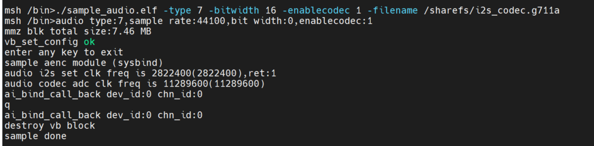
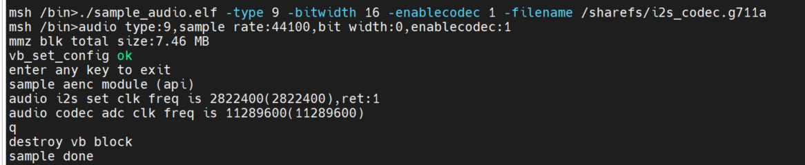
2.5.3.2.5 Encoding Test#
Obtain AI data and encode it to save to a file. Encoding and decoding only support g711a/u, 16bit.
System binding method: ./sample_audio.elf -type 7 -bitwidth 16 -enablecodec 1 -filename /sharefs/i2s_codec.g711a
API interface method: ./sample_audio.elf -type 9 -bitwidth 16 -enablecodec 1 -filename /sharefs/i2s_codec.g711a
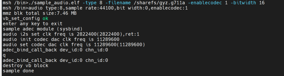
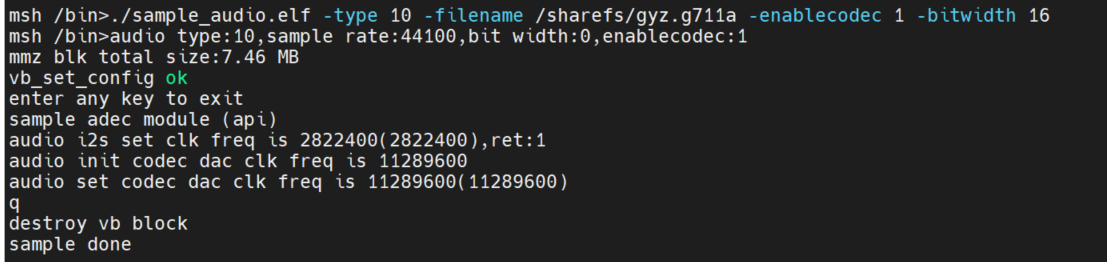
2.5.3.2.6 Decoding Test#
Read file data and decode it for playback. Encoding and decoding only support g711a/u, 16bit.
System binding method: ./sample_audio.elf -type 8 -filename /sharefs/gyz.g711a -enablecodec 1 -bitwidth 16
API interface method: ./sample_audio.elf -type 10 -filename /sharefs/gyz.g711a -enablecodec 1 -bitwidth 16
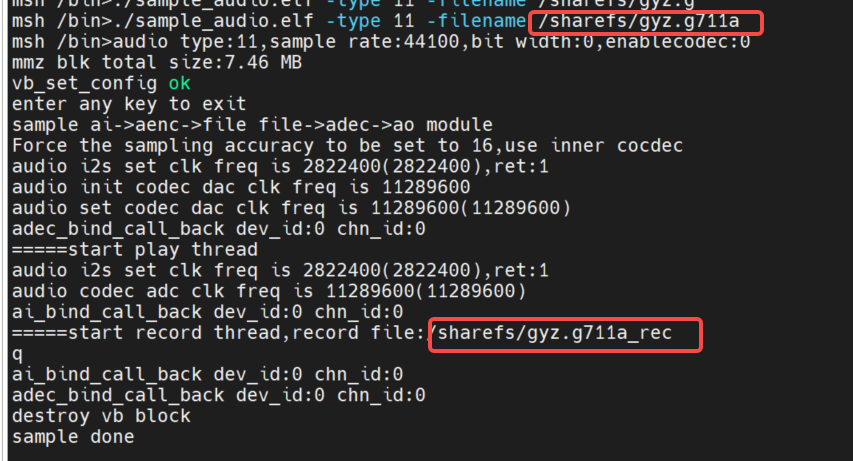
2.5.3.2.7 Full Audio Process Test#
Record module ai->aenc->file and playback module file->adec->ao run simultaneously to simulate a voice intercom scenario. Use the built-in codec with 16bit precision for simulation. Use
-filenameto select the file to be played, which should be in g711a format, and-samplerateto select the sampling precision. The recorded file name will be the playback file name followed by_rec: for instance, if-filenameis/sharefs/test.g711a, the recorded file name will be/sharefs/test.g711a_rec.
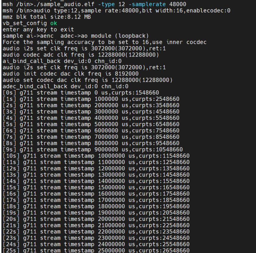
ai->aenc, adec->ao two-way binding loopback test. Use the built-in codec with 16bit precision for simulation.
Simultaneously test the timestamp of the stream after g711 encoding.
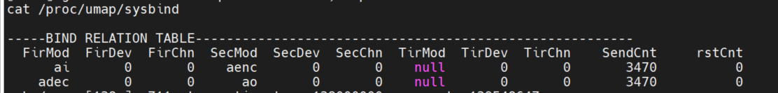
Input cat /proc/umap/sysbind to view the system binding between modules.
2.5.3.2.8 MAPI Audio Test#
Ensure that the large core has started the inter-core communication process: first confirm that the small core has loaded the k_ipcm.ko module, then confirm that the large core has started: /sharefs/app/sample_sys_init.elf &
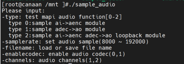
You can input
/mnt/sample_audio -helpto view the demo usage.Use the
-typeoption to test different module functions.Use the
-samplerateoption to configure different sampling rates for audio input and output (8k-192k), default is 44.1k.Use the
-enablecodecoption to use the built-in codec or an external audio sub-board, default is the built-in codec.Use the
-filenameto load or store g711 files.Use
-channelsto specify the number of channels.
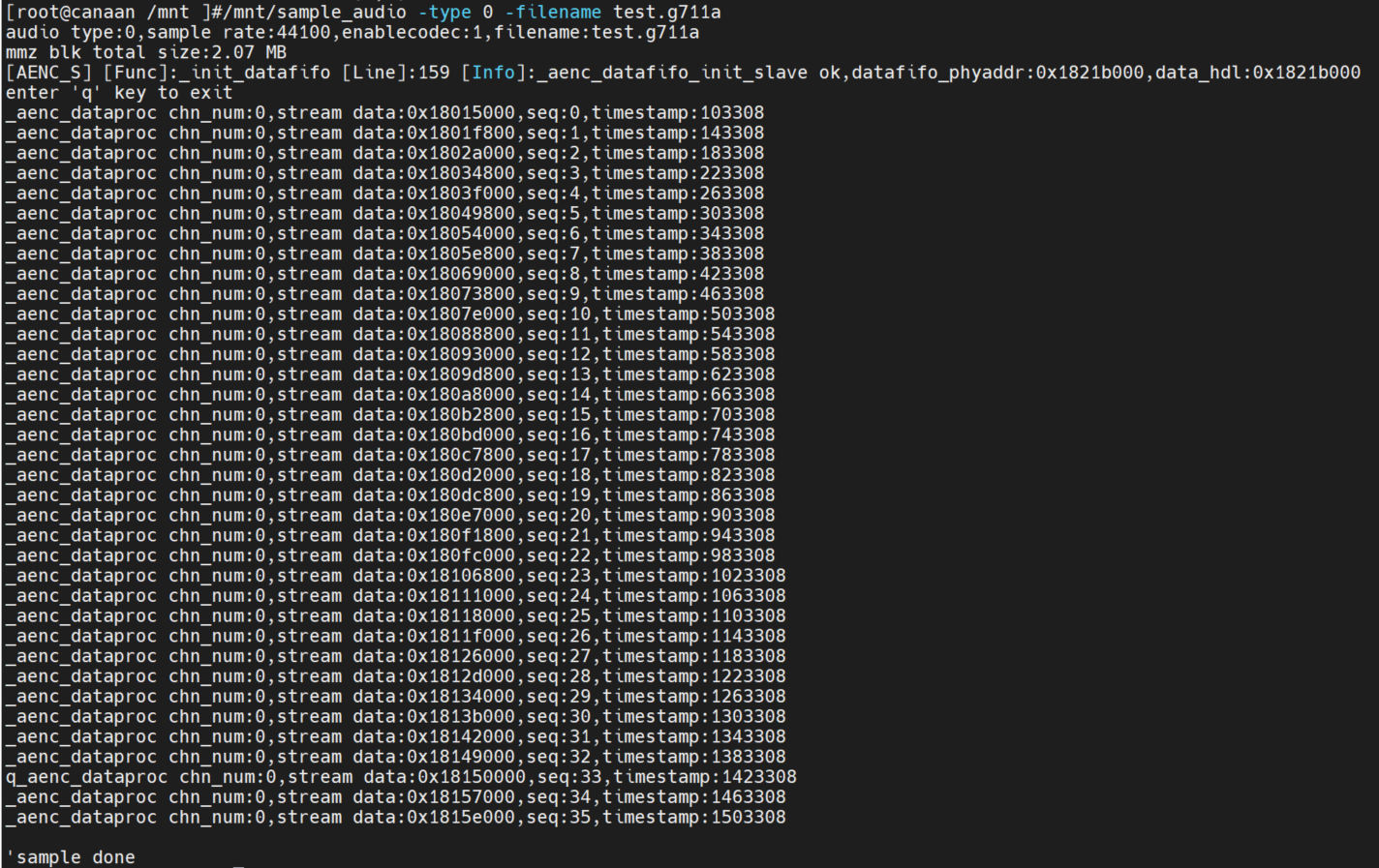
ai->aenc Test
Execute the command on the small core: /mnt/sample_audio -type 0 -filename test.g711a, press the q key to exit the test. The demo can collect audio data in real-time and encode it into g711a format, saving it to a file.
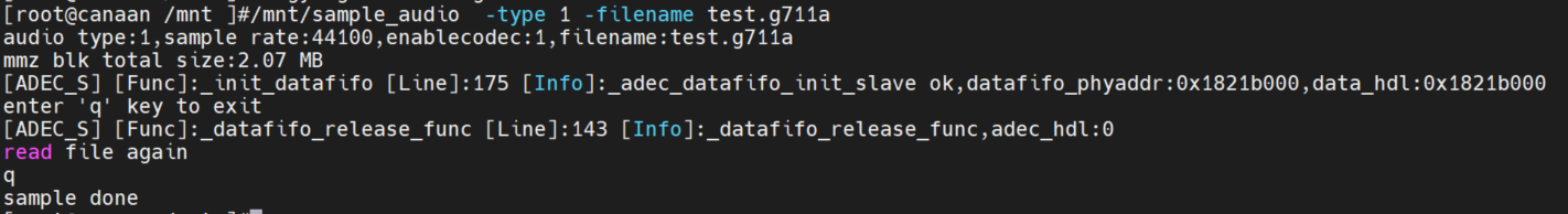
adec->ao Test
Execute the command on the small core: /mnt/sample_audio -type 1 -filename tes.g711a, press the q key to exit the test. The demo can loop decode and play local g711a format files.
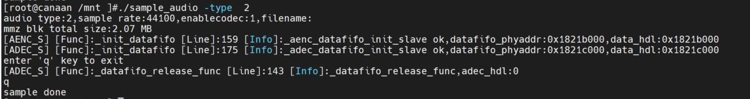
ai->aenc adec->ao Loopback Test
Execute the command on the small core: /mnt/sample_audio -type 2, press the q key to exit the test. The demo can collect audio data in real-time, encode it into g711a format, then decode the g711a format data and play it back.
2.6 Vicap_demo#
2.6.1 Vicap_demo Introduction#
The vicap demo implements camera data collection and preview functions by calling MPI interfaces.
2.6.2 Feature Description#
The CanMV development board uses the OV5647 camera module by default, supporting up to three data streams from a single camera.
2.6.3 Dependency Resources#
Camera module
2.6.4 Usage Instructions#
2.6.4.1 Compilation#
Refer to the README.md in the SDK for the software compilation environment.
Execute
make mpp-clean && rt-smart && make build-imagein the k230_sdk directory to compile the modifications for the large core into the SD card image. The image filesysimage-sdcard.imgwill be generated in thek230_sdk/output/k230_evb_defconfig/images/directory.
2.6.4.2 Execution#
Copy the
src/big/mpp/userapps/sample/elf/sample_vicap.elffile to a specified local directory.Mount this directory to
/sharefson the small core Linux via NFS.On the large core, use the
cd /sharefscommand to enter the/sharefsdirectory.Execute the
./sample_vicapcommand in this directory to get command help information.
When you input the sample_vicap command, the following prompt information will be printed:
usage: ./sample_vicap -mode 0 -dev 0 -sensor 23 -chn 0 -chn 1 -ow 640 -oh 480 -preview 1 -rotation 1      // Canmv-K230-V1.0/1.1 board
usage: ./sample_vicap -mode 0 -dev 0 -sensor 33 -chn 0 -chn 1 -ow 640 -oh 480 -preview 1 -rotation 1      // Canmv-K230-V2.0 board
Options:
 -mode:         vicap work mode[0: online mode, 1: offline mode. only offline mode support multiple sensor input]     default 0
 -dev:          vicap device id[0,1,2]        default 0
 -dw:           enable dewarp[0,1]    default 0
 -sensor:       sensor type[0: ov9732@1280x720, 1: ov9286_ir@1280x720], 2: ov9286_speckle@1280x720]
 -ae:           ae status[0: disable AE, 1: enable AE]        default enable
 -awb:          awb status[0: disable AWB, 1: enable AWb]     default enable
 -chn:          vicap output channel id[0,1,2]        default 0
 -ow:           the output image width, default same with input width
 -oh:           the output image height, default same with input height
 -ox:           the output image start position of x
 -oy:           the output image start position of y
 -crop:         crop enable[0: disable, 1: enable]
 -ofmt:         the output pixel format[0: yuv, 1: rgb888, 2: rgb888p, 3: raw], only channel 0 support raw data, default yuv
 -preview:      the output preview enable[0: disable, 1: enable], only support 2 output channel preview
 -rotation:     display rotation[0: degree 0, 1: degree 90, 2: degree 270, 3: degree 180, 4: unsupported rotation]
 -help:         print this help
Parameter descriptions are as follows:
Parameter Name |
Optional Values |
Parameter Description |
|---|---|---|
-dev |
0: vicap device 0, 1: vicap device 1, 2: vicap device 2 |
Specify the current vicap device in use. The system supports up to three vicap devices. By specifying the device number, the sensor can be bound to different vicap devices. For example: |
-mode |
0: online mode; 1: offline mode |
Specify the vicap device working mode. Currently, both online and offline modes are supported. For multiple sensor inputs, offline mode must be specified. |
-conn |
0: Screen hx8399; 1: HDMI lt9611-1920x1080p60; 2: HDMI lt9611-1920x1080p30 |
Specify the display method, you can choose between screen or HDMI. The default is 0. |
-sensor |
23: OV5647 (Canmv-K230-V1.0/1.1 board), 33: OV5647 (Canmv-K230-V2.0 board) |
Specify the current sensor type in use. |
-chn |
0: vicap device output channel 0, 1: vicap device output channel 1, 2: vicap device output channel 2 |
Specify the current output channel of the vicap device. A vicap device supports up to three outputs, with only channel 0 supporting RAW image format output. |
-ow |
Specify the output image width, default is the input image width. The width needs to be 16-byte aligned. If the default width exceeds the maximum output width of the display screen, the display output width will be used as the final output width. If the output width is less than the input image width and the |
|
-oh |
Specify the output image height, default is the input image height. If the default height exceeds the maximum output height of the display screen, the display output height will be used as the final output height. If the output height is less than the input image height and the |
|
-ox |
Specify the horizontal starting position of the image output. If this parameter is greater than 0, output cropping will be performed. |
|
-oy |
Specify the vertical starting position of the image output. If this parameter is greater than 0, output cropping will be performed. |
|
-crop |
0: disable cropping function, 1: enable cropping function |
When the output image size is smaller than the input image size, it defaults to scaled output. If this flag is specified, it will crop the output. |
-ofmt |
0: yuv format output, 1: rgb format output, 2: raw format output |
Specify the output image format, default is yuv output. |
-preview |
0: disable preview display, 1: enable preview display |
Specify the output image preview display function. Default is enabled. Currently, up to 2 output images can be previewed simultaneously. |
-rotation |
0: rotate 0 degrees, 1: rotate 90 degrees, 2: rotate 180 degrees, 3: rotate 270 degrees, 4: unsupported rotation |
Specify the rotation angle of the preview display window. By default, only the first output image window supports the rotation function. |
Example 1:
./sample_vicap -conn 1 -dev 0 -sensor 23 -chn 0 -chn 1 -ow 640 -oh 480 -preview 0 // Canmv-K230-V1.0/1.1 board
./sample_vicap -conn 1 -dev 0 -sensor 33 -chn 0 -chn 1 -ow 640 -oh 480 -preview 0 // Canmv-K230-V2.0 board
Description: Bind the OV5647@1920x1080 RGB output to vicap device 0, and enable vicap device output channels 0 and 1. Channel 0 output size defaults to the input image size (1920x1080), and channel 1 output image size is 640x480.
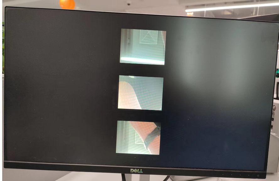
Example 2: OV5647 Triple Camera
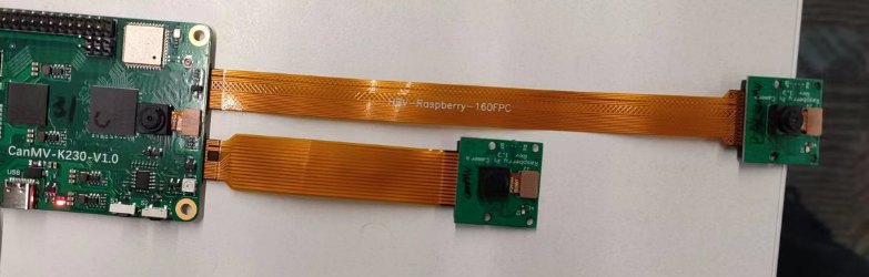
Note: The two OV5647s on the back can use the Raspberry Pi OV5647 camera. The Canmv-K230 V1.0 V1.1 version of the board needs to replace the LDO to 1.8V, such as RT9013-18. As shown below:
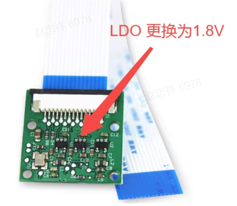
If it is inconvenient to replace the LDO, you can wait for the subsequent V1.2 version of the board.
./sample_vicap.elf -conn 1 -mode 1 -dev 0 -sensor 23 -chn 0 -ow 320 -oh 240 -dev 1 -sensor 26 -chn 0 -ow 320 -oh 240 -dev 2 -sensor 27 -chn 0 -ow 320 -oh 240 -ofmt 1  // Canmv-K230-V1.0/1.1 board

./sample_vicap.elf -conn 1 -mode 1 -dev 0 -sensor 31 -chn 0 -ow 320 -oh 240 -dev 1 -sensor 32 -chn 0 -ow 320 -oh 240 -dev 2 -sensor 33 -chn 0 -ow 320 -oh 240 -ofmt 1  // Canmv-K230-V2.0 board
2.7 DMA_demo#
2.7.1 DMA_demo Introduction#
2.7.1.1 Non-binding Mode#
DMA channels 0-3 are GDMA, and channels 4-7 are SDMA.
Channel 0 continuously inputs images with a resolution of 1920x1080, 8-bit, YUV400, single-channel mode, rotates 90 degrees, and outputs, comparing with golden data.
Channel 1 continuously inputs images with a resolution of 1280x720, 8-bit, YUV420, dual-channel mode, rotates 180 degrees, and outputs, comparing with golden data.
Channel 2 continuously inputs images with a resolution of 1280x720, 10-bit, YUV420, triple-channel mode, x-mirror, y-mirror, and outputs, comparing with golden data.
Channel 4 performs a 1D mode loop transfer of a segment of data, and after the transfer is complete, compares with golden data.
Channel 5 performs a 2D mode loop transfer of a segment of data, and after the transfer is complete, compares with golden data.
2.7.1.2 Binding Mode#
Use VVI as the DMA simulation input. Bind VVI device 0’s channel 0 to DMA channel 0, and VVI device 0’s channel 1 to DMA channel 1. VVI inputs a 640x320, YUV400, 8-bit, 90° rotated image to channel 0 every second, and a 640x320, YUV400, 8-bit, 180° rotated image to channel 1.
2.7.2 Feature Description#
Includes DMA device property configuration, channel property configuration, graphical input, output, release, pipeline binding, and other functions.
2.7.3 Dependency Resources#
None
2.7.4 Usage Instructions#
2.7.4.1 Compilation#
Refer to the README.md in the release SDK package for software compilation.
2.7.4.2 Execution#
Non-binding mode demo execution
/sharefs/app/sample_dma.elf
Test information will be displayed on the screen, and press ‘q’ to end the execution.
Binding mode demo execution
/sharefs/app/sample_dma_bind.elf
Test information will be displayed on the screen, and press ‘q’ to end the execution.
2.8 USB_demo#
2.8.1 USB_demo Introduction#
The USB demo currently includes four functionalities:
As a device, it simulates a USB drive and a mouse/keyboard.
As a host, it connects to a USB drive and a mouse/keyboard.
2.8.2 Feature Description#
The USB demo’s functionalities are natively integrated into the Linux system.
2.8.3 Dependency Resources#
Type-C cable, Type-C to Type-A adapter.
2.8.4 Usage Instructions#
2.8.4.1 Simulating USB Drive as a Device#
# Allocate a memory space to simulate the USB drive's disk space.
[root@canaan / ]#gadget-storage-mem.sh
2+0 records in
2+0 records out
mkfs.fat 4.1 (2017-01-24)
[ 1218.882053] Mass Storage Function, version: 2009/09/11
[ 1218.887308] LUN: removable file: (no medium)
[ 1218.895464] dwc2 91500000.usb-otg: bound driver configfs-gadget
[root@canaan / ]#[ 1219.019554] dwc2 91500000.usb-otg: new device is high-speed
[ 1219.056629] dwc2 91500000.usb-otg: new address 5

# Use the FAT partition of the SD/eMMC as the simulated USB drive's disk space.
[root@canaan ~ ]#gadget-storage.sh
[  359.995510] Mass Storage Function, version: 2009/09/11
[  360.000762] LUN: removable file: (no medium)
[  360.013138] dwc2 91500000.usb-otg: bound driver configfs-gadget
[root@canaan ~ ]#[  360.136809] dwc2 91500000.usb-otg: new device is high-speed
[  360.173543] dwc2 91500000.usb-otg: new address 43
Connect the USB port of the development board to a PC via a Type-C cable. The PC will display a connected USB drive.
2.8.4.2 Connecting USB Drive as a Host#
Connect the USB port of the K230 development board to a USB drive using a Type-C to Type-A adapter.
2.8.4.3 Simulating Mouse/Keyboard as a Device#
Connect the USB port of the K230 development board to another computer using a Type-C cable for testing.
[root@canaan / ]#gadget-hid.sh

[root@canaan / ]#hid_gadget_test /dev/hidg0 mouse
# Enter the corresponding operations based on the prompts, such as -123 -123, and you will see the mouse pointer move on the PC.

[root@canaan / ]#hid_gadget_test /dev/hidg1 keyboard
# Enter the corresponding operations based on the prompts, and you will see keyboard-like input on the PC, such as a b c --return.
2.8.4.4 Connecting Mouse/Keyboard as a Host#
Connect the USB port of the K230 development board to a mouse or keyboard using a Type-C to Type-A adapter.
# Use the following command to determine the event corresponding to the input device. If the K230 development board is not connected to a screen, the event corresponding to the connected mouse/keyboard will change.
[root@canaan ~ ]#cat /proc/bus/input/devices
...
I: Bus=0003 Vendor=046d Product=c52f Version=0111
N: Name="Logitech USB Receiver"
P: Phys=usb-91500000.usb-otg-1/input0
S: Sysfs=/devices/platform/soc/91500000.usb-otg/usb1/1-1/1-1:1.0/0003:046D:C52F.0001/input/input2
U: Uniq=
H: Handlers=event2
B: PROP=0
B: EV=17
B: KEY=ffff0000 0 0 0 0
B: REL=1943
B: MSC=10
[root@canaan / ]$ test_mouse /dev/input/event2
# Click or move the mouse, and the corresponding display will appear in the terminal.

[root@canaan / ]$ test_keyboard /dev/input/event2
# Press different keys on the keyboard, and the corresponding display will appear in the terminal.
2.9 GPU_demo#
2.9.1 GPU_demo Introduction#
The GPU demo includes three executable programs:
tiger: Draws a vector tiger illustration.linearGrad: Draws a linear gradient example.imgIndex: Draws a color lookup table example.
2.9.2 Feature Description#
The GPU demo mainly covers three functions: vector drawing, linear gradient (implemented through pattern), and color lookup table.
2.9.3 Dependency Resources#
Writable file system.
2.9.4 Usage Instructions#
Enter a writable directory and execute the program.
2.9.4.1 tiger#
Run the tiger command, and after execution, a tiger.png file will be generated in the current directory, as shown below:

2.9.4.2 linearGrad#
Run the linearGrad command, and after execution, a linearGrad.png file will be generated in the current directory, as shown below:

2.9.4.3 imgIndex#
Run the imgIndex command, and after execution, four image files will be generated in the current directory, as shown below:
imgIndex1.png: index1 mode, supports 2 colors

imgIndex2.png: index2 mode, supports 4 colors

imgIndex4.png: index4 mode, supports 16 colors

imgIndex8.png: index8 mode, supports 256 colors

2.9.4.4 vglite_drm#
Run the vglite_drm command, and a pattern drawn by the GPU will be displayed on the LCD screen. Press the Enter key again to display the next pattern, as shown below:

2.9.4.5 vglite_cube#
Run the vglite_cube command, and a rotating cube drawn by the GPU will be displayed on the LCD screen, as shown below:

This demo will generate a lot of kernel messages. If you do not want to see these messages, you can lower the kernel log level:
sysctl -w kernel.printk=6
2.10 DRM Display Demo#
2.10.1 Demo Introduction#
This demo runs on the Linux system of the K230 small core, specifically displaying images on the screen.
2.10.2 Feature Description#
DRM supports operations on 5 layers, including: 1 video layer and 4 OSD layers.
The video layer supports NV12, NV21, NV16, NV61 color spaces.
The OSD layer supports ARGB8888, ARGB4444, RGB888, RGB565 color spaces.
2.10.3 Dependency Resources#
HDMI display
2.10.4 Usage Instructions#
2.10.4.1 Compilation#
Refer to the README.md in the release SDK package for software compilation.
2.10.4.2 Execution#
modetest -M canaan-drm -D 0 -a -s 38@36:1920x1080-30 -P 32@36:1920x1080@AR24 -v -F smpte
After executing the above command, color bars will be displayed on the HDMI display, as shown below:

2.11 LVGL Demo#
2.11.1 Demo Introduction#
This demo runs on the Linux system of the K230 small core and displays a configuration interface on the HDMI display.
2.11.3 Dependency Resources#
HDMI display
2.11.3 Usage Instructions#
2.11.3.1 Compilation#
Refer to the README.md in the release SDK package for software compilation.
2.11.3.2 Execution#
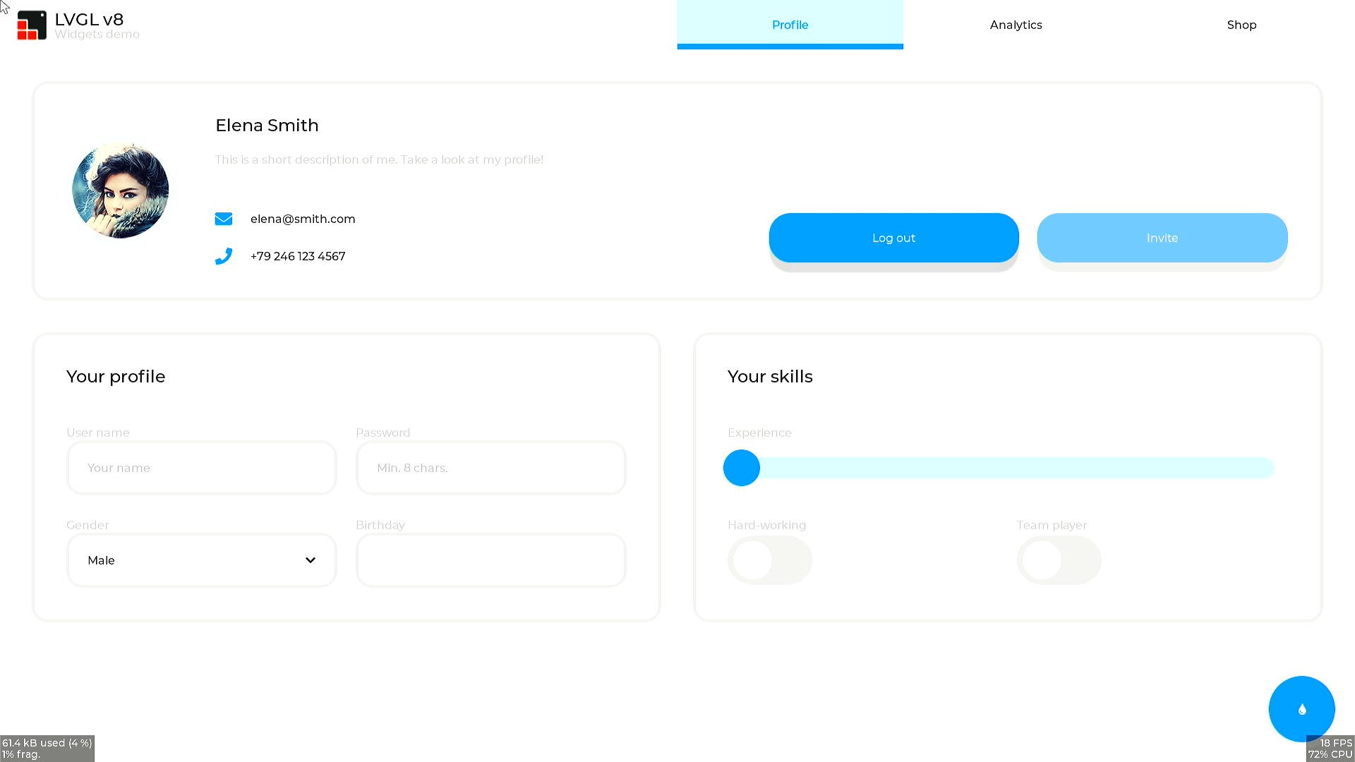
lvgl_demo_widgets
After executing the above command, a configuration interface will be displayed on the HDMI display, as shown below:
2.12 RTSP Streaming Demo#
2.12.1 Demo Introduction#
This demo implements RTSP streaming.
2.12.2 Feature Description#
This demo supports simultaneous streaming of audio and video streams to an RTSP server, using the mapi venc&aenc interface for audio and video encoding. After streaming, you can pull the stream using a URL. Currently, this demo supports streaming and pulling three URLs.
2.12.3 Dependency Resources#
A USB to Ethernet adapter is required to connect the development board to a network cable.
2.12.4 Usage Instructions#
2.12.4.1 Compilation#
Refer to the README.md in the release SDK package for instructions on compiling in the Docker environment. After compilation, the executable program rtsp_demo will be generated in the k230_sdk/src/common/cdk/user/out/little directory.
2.12.4.2 Execution#
The default sensor type used by rtsp_demo is IMX335_MIPI_2LANE_RAW12_1920X1080_30FPS_LINEAR. You can modify the sensor type and other parameters via command line arguments as follows:
After starting the development board:
Use
lsmodto check if thek_ipcmmodule is loaded on the smaller core. If not, load it withinsmod k_ipcm.ko.Start the inter-core communication process on the larger core by executing
./sample_sys_inif.elf.On the smaller core, navigate to the
/mntdirectory and execute./rtsp_demo. By default, it streams one H.265 video with a resolution of 1280x720. For other parameters, refer to the options below. When streaming MJPEG, the maximum supported resolution is 2032x1944, and the minimum is 640x480.
Usage: ./rtsp_demo -s 24 -n 2 -t h265 -w 1280 -h 720 -a 0  // Canmv-K230-V1.0/1.1 board
Usage: ./rtsp_demo -s 39 -n 2 -t h265 -w 1280 -h 720 -a 0  // Canmv-K230-V2.0 board
                    -s: the sensor type:
                        see vicap doc
                    -n: the session number, range: 1, 2, 3
                    -t: the video encoder type: h264/h265/mjpeg
                    -w: the video encoder width
                    -h: the video encoder height
                    -a: audio input type (0: mic input, 1: headphone input): default 0.
Refer to the k230_docs/zh/01_software/board/mpp/K230_Camera_Sensor适配指南.md document for the sensor type values under k_vicap_sensor_type.
The audio input type can be either the onboard mic or headphone input.
Once rtsp_demo is running on the smaller core, it will print a URL like rtsp://ip:8554/session0, where 0 represents the first session. You can use VLC to pull and play the stream from this URL. To stop the stream, first stop VLC and then press ctrl+c to terminate rtsp_demo.
2.13 FaceAeDemo#
2.13.1 Demo Introduction#
This demo runs on the larger core and demonstrates the integration of VICAP, KPU, VO (video output), and AERoi. It can adjust the facial exposure brightness through face detection.
2.13.2 Compilation#
Refer to the README.md in the release SDK for instructions on using Docker to compile the image.
After compilation, the sample (
sample_face_ae.elf) will be located atk230_sdk/src/big/mpp/userapps/sample/elf.Since the KPU linkage requires the detection model
test.kmodel, it will be stored atk230_sdk/src/big/mpp/userapps/sample/elfafter compilation.
2.13.3 Execution#
cd /sharefs/app
./sample_face_ae.elf test.kmodel 1 # arg1: model name, arg2: enable face AE
Wait for initialization to complete and prompt for any letter + enter.
Type 'a' and press enter to run the face AE demo.
Upon successful execution, the physical address of each frame image will be printed.
2.14 FFT Demo#
2.14.1 Demo Introduction#
This demo verifies the usage of FFT APIs and tests the FFT functionality. The code is located at src/big/mpp/userapps/sample/sample_fft/.
2.14.2 Feature Description#
First, an FFT calculation is performed, followed by an IFFT calculation.
2.14.3 Dependency Resources#
None
2.14.4 Usage Instructions#
2.14.4.1 Compilation#
Refer to the README.md in the release SDK package.
2.14.4.2 Execution#
Once both the large and small core systems are up, execute the following command on the larger core:
cd /sharefs/app; ./sample_fft.elf
The larger core serial output will display:
msh /sharefs/app> ./sample_fft.elf 1 0
-----fft ifft point 0064  -------
    max diff 0003 0001
    i=0045 real  hf 0000  hif fc24 org fc21 dif 0003
    i=0003 imag  hf ffff  hif 0001 org 0000 dif 0001
-----fft ifft point 0064 use 133 us result: ok


-----fft ifft point 0128  -------
    max diff 0003 0002
    i=0015 real  hf 0001  hif fca1 org fc9e dif 0003
    i=0031 imag  hf 0001  hif fffe org 0000 dif 0002
-----fft ifft point 0128 use 121 us result: ok


-----fft ifft point 0256  -------
    max diff 0003 0001
    i=0030 real  hf 0000  hif fca1 org fc9e dif 0003
    i=0007 imag  hf ffff  hif 0001 org 0000 dif 0001
-----fft ifft point 0256 use 148 us result: ok


-----fft ifft point 0512  -------
    max diff 0003 0003
    i=0060 real  hf 0000  hif fca1 org fc9e dif 0003
    i=0314 imag  hf 0001  hif fffd org 0000 dif 0003
-----fft ifft point 0512 use 206 us result: ok


-----fft ifft point 1024  -------
    max diff 0005 0002
    i=0511 real  hf 0000  hif fc00 org fc05 dif 0005
    i=0150 imag  hf 0000  hif fffe org 0000 dif 0002
-----fft ifft point 1024 use 328 us result: ok


-----fft ifft point 2048  -------
    max diff 0005 0003
    i=1022 real  hf 0000  hif fc00 org fc05 dif 0005
    i=1021 imag  hf 0000  hif 0003 org 0000 dif 0003
-----fft ifft point 2048 use 574 us result: ok


-----fft ifft point 4096  -------
    max diff 0005 0002
    i=4094 real  hf 027b  hif 041f org 0424 dif 0005
    i=0122 imag  hf 0000  hif 0002 org 0000 dif 0002
-----fft ifft point 4096 use 1099 us result: ok
2.15 SDIO WIFI#
2.15.1 Demo Introduction#
The CANMV development board uses an SDIO WIFI module that supports 2.4G, specifically the AP6212. It supports both STA and softAP modes.
2.15.2 Compilation#
The default configuration for building CANMV in k230_sdk supports AP6212 WIFI.
Run make menuconfig:
K230 SDK Configuration
    wifi configurations  --->
        [*] enable ap6212a
Once ap6212a is enabled, k230_sdk will copy the necessary firmware or nvram configuration to the file system.
Run make linux-menuconfig:
Linux/riscv 5.10.4 Kernel Configuration
    Device Drivers  --->
        [*] Network device support  --->
            [*]   Wireless LAN  --->
                <M>   Broadcom FullMAC wireless cards support
                (/etc/firmware/fw_bcm43456c5_ag.bin) Firmware path
                (/etc/firmware/nvram.txt) NVRAM path
                    Enable Chip Interface (SDIO bus interface support)  --->
                    Interrupt type (In-Band Interrupt)  --->
Configure the LINUX build for the WIFI driver. The default mode for CANMV WIFI is STA and softAP coexistence. The source code path is:
src/little/linux/drivers/net/wireless/bcmdhd
Run make buildroot-menuconfig:
Buildroot 2021.02-git Configuration
    Target packages  --->
        Networking applications  --->
            [*] hostapd
            [*]   Enable hostap driver
            [*]   Enable nl80211 driver
            [ ]   Enable wired driver
            [*]   Enable ACS
            [*]   Enable EAP
            [*]   Enable WPS
            [*]   Enable WPA3 support
            [*]   Enable VLAN support
            [*]     Enable dynamic VLAN support
            [*]     Use netlink-based API for VLAN operations

            [*] wireless tools
                [*]   Install shared library

            [*] wpa_supplicant
                [*]   Enable nl80211 support
                [*]   Enable AP mode
                [*]     Enable Wi-Fi Display
                [*]     Enable mesh networking
                [*]   Enable autoscan
                [*]   Enable EAP
                [*]   Enable HS20
                [*]   Enable syslog support
                [*]   Enable WPS
                [*]   Enable WPA3 support
                [*]   Install wpa_clibinary
                [ ]   Install wpa_client shared library
                [*]   Install wpa_passphrase binary
                [*]   Enable support for the DBus control interface
Compile buildroot to add wireless tools.
The WIFI module is reset during system startup in uboot. Source code:
src/little/uboot/board/canaan/k230_canmv/board.c : board_late_init
The WIFI module is powered on/off via if wlan down/up after system startup. Source code:
&gpio1 {
    status = "okay";
};

&mmc_sd0 {
    status = "okay";
    io_fixed_1v8;
    rx_delay_line = <0x00>;
    tx_delay_line = <0x00>;
    bcmdhd_wlan {
        compatible = "android,bcmdhd_wlan";
        gpio_wl_reg_on = <&port1 0 GPIO_ACTIVE_HIGH>;
    };
};
2.14.5 Execution#
STA (Station) mode is where the device acts as a client and connects to an AP (Access Point) for network access. Our mobile phones typically operate in STA mode when connecting to a router.
AP mode is where the device acts as a server, providing wireless access to other devices. Wireless routers, gateways, and hotspots typically operate in AP mode, allowing other devices to connect and communicate through it.
2.14.5.1 STA Testing#
ifconfig -a
ifconfig wlan0 up
wpa_supplicant -D nl80211 -i wlan0 -c /etc/wpa_supplicant.conf -B
wpa_cli -i wlan0 scan
wpa_cli -i wlan0 scan_result
wpa_cli -i wlan0 add_network
wpa_cli -i wlan0 set_network 1 psk '"12345678"'
wpa_cli -i wlan0 set_network 1 ssid '"wifi_test"'
wpa_cli -i wlan0 select_network 1
udhcpc -i wlan0 -q
2.14.5.2 AP Testing#
[root@canaan ~ ]#cat /etc/hostapd.conf
ctrl_interface=/var/run/hostapd
driver=nl80211
ieee80211n=1
interface=wlan1
hw_mode=g
channel=6
beacon_int=100
dtim_period=1
ssid=k230_ap
auth_algs=1
ap_isolate=0
ignore_broadcast_ssid=0
ifconfig wlan1 192.168.1.1
udhcpd /etc/udhcpd.conf &
hostapd /etc/hostapd.conf &
A STA device can connect directly to the k230_ap hotspot without a password.
2.15 UVC_demo#
2.15.1 uvc_demo Introduction#
The UVC demo turns the K230 development board into a USB camera. When connected to a PC via a USB cable, the PC’s player can display the real camera image.
2.15.2 Feature Description#
The current version supports both bulk and ISO transfer.
It supports 640x480 NV12 format images and 1280x720 H264/MJPEG format images.
PID, VID, and device name can be configured by modifying the shell script.
2.15.3 Dependency Resources#
Type-C cable to connect USB0 to the PC.
A camera application on the PC or PotPlayer software.
2.15.4 Usage Instructions#
2.15.4.1 Compilation#
Refer to the README.md in the SDK for the software compilation environment.
The user program source code for the smaller core is located at
cdk/user/mapi/sample/camera.The driver program for the smaller core is located at
linux/drivers/usb/dwc2.The driver program for the smaller core is located at
linux/drivers/usb/gadget.The larger core program involves the
mpprepository andcdk.
The larger core’s RTT implements the camera driver functionality.
The smaller core’s Linux implements the USB driver functionality and obtains camera images from the larger core via mapi.
Refer to K230_USB_Application_Practice_UVC_Transmission_YUV_and_Encoding_Stream.
2.15.4.2 Execution#
After entering the large core RT-Smart system, navigate to the /bin directory and execute:
msh /sharefs/app> ./sample_sys_init.elf
After entering the small core Linux system, navigate to the /mnt directory and execute:
./canaan-camera.sh start otg0

./camera -t 24
Connect the Type-C USB cable to USB0 and the PC, and use PotPlayer to play the camera.
By default, it uses BULK transfer. You can change to ISO transfer with the following command.
./canaan-camera.sh stop

./canaan-camera.sh start otg0 iso

./camera -i -t 24  // Canmv-K230-V1.0/1.1 board
./camera -i -t 39  // Canmv-K230-V2.0 board
The -t option is used to specify the vicap sensor type. Please refer to the k230_docs/zh/01_software/board/mpp/K230_Camera_Sensor适配指南.md document for the description of k_vicap_sensor_type. For CanMV, it should be set to 24.
Go to PotPlayer -> Options -> Device -> Camera interface,
Video Recording Device -> Device, select UVC Camera
Video Recording Device -> Format, select H264 1280*720 30(P 16:9) or MJPG 1280*720 30(P 16:9) or NV12 640*360p 30(P 16:9)
PotPlayer -> Open -> Camera/Other Device
2.16 YUV Sensor Demo#
2.16.1 Demo Introduction#
Three-way YUV sensor input, outputting YUV444 packed format to DDR through VICAP’s MCM hardware, and converting to NV12 format using the CSC function of nonai_2d hardware.
VICAP binds to nonai_2d, nonai_2d outputs to both VENC and VO, performing RTSP streaming and screen display.
2.16.2 Feature Description#
Only supports 1280x720 resolution.
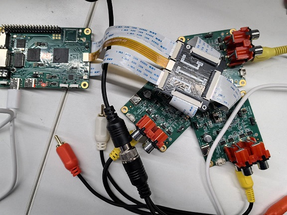
2.16.3 Dependency Resources#
Depends on special adapter board hardware, as shown below:
2.16.4 Usage Instructions#
After entering the large core RT-Smart system, execute:
/sharefs/app/sample_yuv_sensor.elf
After entering the small core Linux system, execute:
/mnt/yuv_sensor_demo -n 3
When rtsp_demo runs normally on the small core, it will print a URL like: rtsp://10.100.228.150:8554/BackChannelTest0, where 0 represents the first channel. You can use VLC to pull and play the stream from this URL, or connect to HDMI output to watch on the screen.