K230 Camera Sensor Adaptation Guide#
Preface#
Overview#
This document mainly describes the K230 platform Camera Sensor framework and how to add support for a new Camera Sensor.
Target Audience#
This document (this guide) is mainly intended for the following personnel:
Technical Support Engineers
Software Development Engineers
Acronyms and Definitions#
Acronym |
Description |
|---|---|
Revision History#
Document Version |
Description of Changes |
Author |
Date |
|---|---|---|---|
V1.0 |
Initial version |
Wang Chenggen |
2023-05-30 |
V1.1 |
Example modified to ov5647 and added section 4.4 |
Zhao Zhongxiang |
2023-04-11 |
1. Overview#
This document mainly describes the basic framework of the K230 platform Camera Sensor and how to add support for a new Camera Sensor.
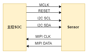
The K230 platform supports various types of sensor interfaces. We will explain using the currently most commonly used MIPI CSI interface Sensor as an example. The hardware connection diagram between the Sensor and the main control platform is as follows:

The main control sends configuration registers through the I2C interface to control the working mode of the sensor, and the sensor sends image data to the main control SOC through the MIPI CSI interface.
2. Camera Sensor Framework#
2.1 Framework Introduction#
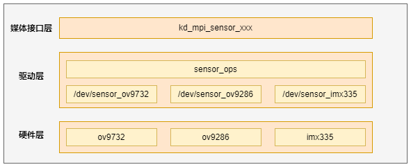
The Camera Sensor framework is shown in Figure 2-1. The lowest layer is the sensor driver layer.

Figure 2-1 Camera Sensor Framework
From top to bottom, the layers are: Media Interface Layer, Driver Layer, and Hardware Layer.
Media Interface Layer: This layer provides the kd_mpi_sensor_xxx interface to external modules for operating and accessing sensor devices, and uses ioctl to operate specific sensor devices.
Driver Layer: This layer includes the common operation interfaces of specific sensor device drivers. The common operation interfaces mainly include ioctl operation commands and sensor I2C read-write interfaces. The sensor driver mainly provides device nodes and the implementation of operation interfaces. This part is also the main work of sensor adaptation.
Hardware Layer: Corresponds to each specific sensor hardware.
3. Sensor Adaptation Preparations#
Before adapting a new sensor, users need to do the following preparations:
Obtain the Sensor datasheet and initialization sequence from legitimate channels.
Review the Sensor datasheet and related application manuals, paying particular attention to Sensor exposure, gain control methods, exposure and gain limitations under different modes, long exposure implementation methods, black level values, Bayer data output order, etc.
Request the required mode initialization sequence from the Sensor manufacturer, and understand the data rate of each sequence, the total width and height of the Sensor output, and the exact frame rate.
Confirm whether the Sensor control interface is I2C, SPI, or other interfaces, and the Sensor device address can be set through hardware. For scenarios with multiple cameras, try not to reuse the I2C bus for sensors. The Sensor IO level in different scenarios may be 1.8V or 3.3V. During design, ensure that the Sensor IO level matches the GPIO power supply voltage of the SOC. For example, if the Sensor level is 1.8V, the GPIO used for Sensor control, such as Reset, I2C, PRDN, needs to use a 1.8V power supply.
Confirm the Sensor output data interface and protocol type. Currently, only the MIPI CSI interface is supported.
Confirm whether the WDR mode is VC, DT, or DOL, etc.
Confirm whether image cropping is required for different timings.
4. Sensor Adaptation Example#
This section will provide a detailed description of the steps to add support for a new camera sensor.
Here, the ov5647 driver is used as an example. The corresponding driver file source code path is as follows:
src/big/mpp/kernel/sensor/src/ov5647_drv.c
4.1 Define Supported Sensor Types#
The Sensor types supported by the system are defined by the following enumeration variable:
typedef enum {
    OV_OV9732_MIPI_1280X720_30FPS_10BIT_LINEAR = 0,
    OV_OV9286_MIPI_1280X720_30FPS_10BIT_LINEAR_IR = 1,
    OV_OV9286_MIPI_1280X720_30FPS_10BIT_LINEAR_SPECKLE = 2,

    OV_OV9286_MIPI_1280X720_60FPS_10BIT_LINEAR_IR = 3,
    OV_OV9286_MIPI_1280X720_60FPS_10BIT_LINEAR_SPECKLE = 4,

    OV_OV9286_MIPI_1280X720_30FPS_10BIT_LINEAR_IR_SPECKLE = 5,
    OV_OV9286_MIPI_1280X720_60FPS_10BIT_LINEAR_IR_SPECKLE = 6,

    IMX335_MIPI_2LANE_RAW12_1920X1080_30FPS_LINEAR = 7,
    IMX335_MIPI_2LANE_RAW12_2592X1944_30FPS_LINEAR = 8,
    IMX335_MIPI_4LANE_RAW12_2592X1944_30FPS_LINEAR = 9,
    IMX335_MIPI_2LANE_RAW12_1920X1080_30FPS_MCLK_7425_LINEAR = 10,
    IMX335_MIPI_2LANE_RAW12_2592X1944_30FPS_MCLK_7425_LINEAR = 11,
    IMX335_MIPI_4LANE_RAW12_2592X1944_30FPS_MCLK_7425_LINEAR = 12,

    IMX335_MIPI_4LANE_RAW10_2XDOL = 13,
    IMX335_MIPI_4LANE_RAW10_3XDOL = 14,

    SC_SC035HGS_MIPI_1LANE_RAW10_640X480_120FPS_LINEAR = 15,
    SC_SC035HGS_MIPI_1LANE_RAW10_640X480_60FPS_LINEAR = 16,
    SC_SC035HGS_MIPI_1LANE_RAW10_640X480_30FPS_LINEAR = 17,

    OV_OV9286_MIPI_1280X720_30FPS_10BIT_MCLK_25M_LINEAR_SPECKLE = 18,
    OV_OV9286_MIPI_1280X720_30FPS_10BIT_MCLK_25M_LINEAR_IR = 19,
    OV_OV9732_MIPI_1280X720_30FPS_10BIT_MCLK_16M_LINEAR = 20,

    OV_OV5647_MIPI_1920X1080_30FPS_10BIT_LINEAR = 21,
    OV_OV5647_MIPI_2592x1944_10FPS_10BIT_LINEAR = 22,
    OV_OV5647_MIPI_640x480_60FPS_10BIT_LINEAR = 23,
    OV_OV5647_MIPI_CSI0_1920X1080_30FPS_10BIT_LINEAR = 24,

    SC_SC201CS_MIPI_1LANE_RAW10_1600X1200_30FPS_LINEAR = 25,
    SC_SC201CS_SLAVE_MODE_MIPI_1LANE_RAW10_1600X1200_30FPS_LINEAR = 26,

    OV_OV5647_MIPI_CSI1_1920X1080_30FPS_10BIT_LINEAR = 27,
    OV_OV5647_MIPI_CSI2_1920X1080_30FPS_10BIT_LINEAR = 28,

    XS9922B_MIPI_CSI0_1280X720_30FPS_YUV422_DOL3 = 29,

    XS9950_MIPI_CSI0_1280X720_30FPS_YUV422 = 30,
    XS9950_MIPI_CSI1_1280X720_30FPS_YUV422 = 31,
    XS9950_MIPI_CSI2_1280X720_30FPS_YUV422 = 32,
    XS9950_MIPI_CSI0_1920X1080_30FPS_YUV422 = 33,

    OV_OV9286_MIPI_1280X720_30FPS_10BIT_MCLK_25M_LINEAR_SPECKLE_V2 = 34,
    OV_OV9286_MIPI_1280X720_30FPS_10BIT_MCLK_25M_LINEAR_IR_V2 = 35,
    OV_OV9732_MIPI_1280X720_30FPS_10BIT_MCLK_16M_LINEAR_V2 = 36,

    OV_OV5647_MIPI_CSI0_1920X1080_30FPS_10BIT_LINEAR_V2 = 37,
    OV_OV5647_MIPI_CSI1_1920X1080_30FPS_10BIT_LINEAR_V2 = 38,
    OV_OV5647_MIPI_CSI2_1920X1080_30FPS_10BIT_LINEAR_V2 = 39,

    GC2053_MIPI_CSI0_1920X1080_30FPS_10BIT_LINEAR = 40,

    SENSOR_TYPE_MAX,
} k_vicap_sensor_type;
When adding new sensor support types, users need to first add the corresponding type definition here. This type is the only identifier for the application program to obtain sensor configuration.
4.2 Sensor Driver Adaptation#
Sensor driver adaptation is the most critical part of the entire process. Users can copy existing sensor driver files for modification. The AE-related register configuration and calculation methods for the sensor need to be reviewed in the corresponding manual or seek professional assistance.
4.2.1 Define Sensor Register Configuration List#
Sensor register configuration is defined by the data type k_sensor_reg_list:
typedef struct {
    k_u16 reg_addr;
    k_u8  reg_val;
} k_sensor_reg_list;
Below is the register configuration list for ov5647:
static const k_sensor_reg ov5647_mipi2lane_1080p_30fps_linear[] = {
    //pixel_rate = 81666700
    {0x0103, 0x01},
    {0x0100, 0x00},
    {0x3034, 0x1a},
    {0x3035, 0x21},
    ...
    {0x3501, 0x02},
    {0x3502, 0xa0},
    {0x3503, 0x07},
    {0x350b, 0x10},
    {REG_NULL, 0x00},
};
4.2.2 Define Supported Sensor Modes#
Sensor mode parameters are defined by the data type k_sensor_mode:
typedef struct {
    k_u32 index;
    k_vicap_sensor_type sensor_type;
    k_sensor_size size;
    k_u32 fps;
    k_u32 hdr_mode;
    k_u32 stitching_mode;
    k_u32 bit_width;
    k_sensor_data_compress compress;
    k_u32 bayer_pattern;
    k_sensor_mipi_info mipi_info;
    k_sensor_ae_info ae_info;
    k_sensor_reg_list *reg_list;
} k_sensor_mode;
Below are the supported modes for ov5647:
static k_sensor_mode ov5647_mode_info[] = {
    {
        .index = 0,
        .sensor_type = OV_OV5647_MIPI_1920X1080_30FPS_10BIT_LINEAR,
        .size = {
            .bounds_width = 1920,
            .bounds_height = 1080,
            .top = 0,
            .left = 0,
            .width = 1920,
            .height = 1080,
        },
    ......
}
4.2.3 Implement Sensor Operation Interfaces#
The sensor operation interfaces are defined by the data type k_sensor_function. Users should implement the relevant operation interfaces according to actual conditions, although not all interfaces must be implemented.
Translation to English#
typedef struct {
    k_s32 (*sensor_power) (void *ctx, k_s32 on);
    k_s32 (*sensor_init) (void *ctx, k_sensor_mode mode);
    k_s32 (*sensor_get_chip_id)(void *ctx, k_u32 *chip_id);
    k_s32 (*sensor_get_mode)(void *ctx, k_sensor_mode *mode);
    k_s32 (*sensor_set_mode)(void *ctx, k_sensor_mode mode);
    k_s32 (*sensor_enum_mode)(void *ctx, k_sensor_enum_mode *enum_mode);
    k_s32 (*sensor_get_caps)(void *ctx, k_sensor_caps *caps);
    k_s32 (*sensor_conn_check)(void *ctx, k_s32 *conn);
    k_s32 (*sensor_set_stream)(void *ctx, k_s32 enable);
    k_s32 (*sensor_get_again)(void *ctx, k_sensor_gain *gain);
    k_s32 (*sensor_set_again)(void *ctx, k_sensor_gain gain);
    k_s32 (*sensor_get_dgain)(void *ctx, k_sensor_gain *gain);
    k_s32 (*sensor_set_dgain)(void *ctx, k_sensor_gain gain);
    k_s32 (*sensor_get_intg_time)(void *ctx, k_sensor_intg_time *time);
    k_s32 (*sensor_set_intg_time)(void *ctx, k_sensor_intg_time time);
    k_s32 (*sensor_get_exp_parm)(void *ctx, k_sensor_exposure_param *exp_parm);
    k_s32 (*sensor_set_exp_parm)(void *ctx, k_sensor_exposure_param exp_parm);
    k_s32 (*sensor_get_fps)(void *ctx, k_u32 *fps);
    k_s32 (*sensor_set_fps)(void *ctx, k_u32 fps);
    k_s32 (*sensor_get_isp_status)(void *ctx, k_sensor_isp_status *status);
    k_s32 (*sensor_set_blc)(void *ctx, k_sensor_blc blc);
    k_s32 (*sensor_set_wb)(void *ctx, k_sensor_white_balance wb);
    k_s32 (*sensor_get_tpg)(void *ctx, k_sensor_test_pattern *tpg);
    k_s32 (*sensor_set_tpg)(void *ctx, k_sensor_test_pattern tpg);
    k_s32 (*sensor_get_expand_curve)(void *ctx, k_sensor_compand_curve *curve);
    k_s32 (*sensor_get_otp_data)(void *ctx, void *data);
} k_sensor_function;
The following are the supported modes for ov5647
    .sensor_func = {
        .sensor_power = ov5647_sensor_power_on,
        .sensor_init = ov5647_sensor_init,
        .sensor_get_chip_id = ov5647_sensor_get_chip_id,
        .sensor_get_mode = ov5647_sensor_get_mode,
        .sensor_set_mode = ov5647_sensor_set_mode,
        .sensor_enum_mode = ov5647_sensor_enum_mode,
        .sensor_get_caps = ov5647_sensor_get_caps,
        .sensor_conn_check = ov5647_sensor_conn_check,
        .sensor_set_stream = ov5647_sensor_set_stream,
        .sensor_get_again = ov5647_sensor_get_again,
        .sensor_set_again = ov5647_sensor_set_again,
        .sensor_get_dgain = ov5647_sensor_get_dgain,
        .sensor_set_dgain = ov5647_sensor_set_dgain,
        .sensor_get_intg_time = ov5647_sensor_get_intg_time,
        .sensor_set_intg_time = ov5647_sensor_set_intg_time,
        .sensor_get_exp_parm = ov5647_sensor_get_exp_parm,
        .sensor_set_exp_parm = ov5647_sensor_set_exp_parm,
        .sensor_get_fps = ov5647_sensor_get_fps,
        .sensor_set_fps = ov5647_sensor_set_fps,
        .sensor_get_isp_status = ov5647_sensor_get_isp_status,
        .sensor_set_blc = ov5647_sensor_set_blc,
        .sensor_set_wb = ov5647_sensor_set_wb,
        .sensor_get_tpg = ov5647_sensor_get_tpg,
        .sensor_set_tpg = ov5647_sensor_set_tpg,
        .sensor_get_expand_curve = ov5647_sensor_get_expand_curve,
        .sensor_get_otp_data = ov5647_sensor_get_otp_data,
    },
4.2.4 Define the sensor driver structure#
The sensor driver structure is defined by struct sensor_driver_dev, which mainly includes sensor I2C configuration information, sensor driver name, and sensor operation set.
struct sensor_driver_dev {
    k_sensor_i2c_info i2c_info;
    k_u8 *sensor_name;
    k_sensor_function sensor_func;
    k_sensor_mode *sensor_mode;
    k_sensor_ae_info ae_info;
    k_s32 pwd_gpio;
    k_s32 reset_gpio;
};
The definition and initialization of the ov5647 driver structure are as follows:
struct sensor_driver_dev ov5647_sensor_drv = {
    .i2c_info = {
        .i2c_bus = NULL,
        .i2c_name = OV5647_IIC,
        .slave_addr = 0x36,
        .reg_addr_size = SENSOR_REG_VALUE_16BIT,
        .reg_val_size = SENSOR_REG_VALUE_8BIT,
    },
    .sensor_name = "ov5647",
    .sensor_func = {
        .sensor_power = ov5647_sensor_power_on,
        .sensor_init = ov5647_sensor_init,
        .sensor_get_chip_id = ov5647_sensor_get_chip_id,
        .sensor_get_mode = ov5647_sensor_get_mode,
        .sensor_set_mode = ov5647_sensor_set_mode,
        ......
    },
};
4.2.5 Update the sensor driver list#
Add the sensor driver structure defined in the previous section to the sensor_drv_list array in sensor_common.c. The currently supported sensor list in the system is as follows:
struct sensor_driver_dev *sensor_drv_list[SENSOR_NUM_MAX] = {
    &ov9732_sensor_drv,
    &ov9286_sensor_drv,
    &imx335_sensor_drv,
    &sc035hgs_sensor_drv,
    &ov5647_sensor_drv,
};
4.3 Update the sensor configuration information list#
The sensor configuration information is defined by the structure k_vicap_sensor_info:
typedef struct {
    const char *sensor_name; /*sensor name*/
    const char *calib_file; /*sensor calibration file name*/
    k_u16 width; /*sensor output image width*/
    k_u16 height; /*sensor output image height*/
    k_vicap_csi_num csi_num; /*CSI bus number used by the sensor hardware connection*/
    k_vicap_mipi_lanes mipi_lanes; /*Number of MIPI LANEs used by the sensor hardware connection*/
    k_vicap_data_source source_id; /*Data source ID*/
    k_bool is_3d_sensor; /*Whether it is a 3D sensor*/

    k_vicap_mipi_phy_freq phy_freq; /*MIPI PHY rate*/
    k_vicap_csi_data_type data_type; /*CSI data type*/
    k_vicap_hdr_mode hdr_mode; /*HDR mode*/
    k_vicap_vi_flash_mode flash_mode; /*flash mode selection*/
    k_vicap_vi_first_frame_sel first_frame;
    k_u16 glitch_filter;
    k_vicap_sensor_type sensor_type; /*sensor type*/
} k_vicap_sensor_info;
The configuration information corresponding to ov5647 in userapps/src/sensor/mpi_sensor.c:
const k_vicap_sensor_info sensor_info_list[] = {
    {
        "ov5647",
        1920,
        1080,
        VICAP_CSI2,
        VICAP_MIPI_2LANE,
        VICAP_SOURCE_CSI2,
        K_TRUE,
        VICAP_MIPI_PHY_800M,
        VICAP_CSI_DATA_TYPE_RAW10,
        VICAP_LINERA_MODE,
        VICAP_FLASH_DISABLE,
        VICAP_VI_FIRST_FRAME_FS_TR0,
        0,
        OV_OV5647_MIPI_1920X1080_30FPS_10BIT_LINEAR,
    },
Each time a sensor configuration mode is added, a corresponding configuration item needs to be added to the sensor_info_list structure.
4.4 Add sensor configuration files#
The current SDK version sensor configuration files include XML files and JSON files, and the file storage path is as follows:
src/big/mpp/userapps/src/sensor/config/
The configuration files corresponding to ov5647 are as follows:
ov5647.xml ov5647_auto.json ov5647_manual.json
For newly added sensors, you can copy and modify existing files to support them. The calibration and tuning parameters can be modified and exported using related tools.
4.5 Porting existing sensor drivers#
If re-designing the board, the sensor’s reset, shutdown, CSI, and I2C may generally be modified. Still taking the ov5647 of canmv as an example.
The reset of ov5647 uses GPIO0 of K230, and I2C uses i2c3.
int ov5647_power_rest(k_s32 on)
{
    rt_kprintf("ov5647_power_rest OV5647_CAM_PIN is %d \n", OV5647_CAM_PIN);
    // rst
    kd_pin_mode(OV5647_CAM_PIN, GPIO_DM_OUTPUT);
    kd_pin_write(OV5647_CAM_PIN, GPIO_PV_HIGH);

    if (on)
    {
        rt_thread_mdelay(DELAY_MS_SENSOR_DEFAULT);
        kd_pin_write(OV5647_CAM_PIN, GPIO_PV_LOW);  //GPIO_PV_LOW  GPIO_PV_HIGH
        rt_thread_mdelay(DELAY_MS_SENSOR_DEFAULT);
        kd_pin_write(OV5647_CAM_PIN, GPIO_PV_HIGH);
    }
struct sensor_driver_dev ov5647_sensor_drv = {
    .i2c_info = {
        .i2c_bus = NULL,
        .i2c_name = OV5647_IIC, // "i2c3"
        .slave_addr = 0x36,
        .reg_addr_size = SENSOR_REG_VALUE_16BIT,
        .reg_val_size = SENSOR_REG_VALUE_8BIT,
    },
OV5647_CAM_PIN and OV5647_IIC are defined in mpp/include/comm/k_board_config_comm.h. This header file configures the variables in the driver based on the board type.
#elif defined(CONFIG_BOARD_K230_CANMV)
#define DISPLAY_LCD_RST_GPIO                            20
#define DISPLAY_LCD_BACKLIGHT_EN                        25
#define VICAP_IMX335_RST_GPIO                           46
#define VICAP_IMX335_MASTER_GPIO                        28
#define VICAP_OV9286_RST_GPIO                           23
#define OV5647_IIC "i2c3"
#define OV5647_CAM_PIN                                  0
If the reset or i2c changes, it can be modified directly in the driver or in this header file.
If there is a change in the use of CSI, for example, changing CSI0 to CSI1, you can modify it in mpp/userapps/src/sensor/mpi_sensor.c
    static const k_vicap_sensor_info sensor_info_list[] = {
        {
            "ov5647",
            1920,
            1080,
            VICAP_CSI0,
            VICAP_MIPI_2LANE,
            VICAP_SOURCE_CSI0,
            K_TRUE,
            VICAP_MIPI_PHY_800M,
            VICAP_CSI_DATA_TYPE_RAW10,
            VICAP_LINERA_MODE,
            VICAP_FLASH_DISABLE,
            VICAP_VI_FIRST_FRAME_FS_TR0,
            0,
            OV_OV5647_MIPI_CSI0_1920X1080_30FPS_10BIT_LINEAR_V2,
        },
    }
Change VICAP_CSI0 and VICAP_SOURCE_CSI0 to VICAP_CSI1 and VICAP_SOURCE_CSI1.