K230 SDK Dewarp User Guide#
Preface#
Overview#
This document mainly introduces the calibration and usage methods of the Dewarp module in the K230 VICAP module.
Target Audience#
This document (guide) is mainly intended for the following personnel:
Technical Support Engineers
Software Development Engineers
Abbreviation Definitions#
Abbreviation |
Description |
|---|---|
DW |
Dewarp |
Revision History#
Document Version |
Description |
Author(s) |
Date |
|---|---|---|---|
V1.0 |
Initial Version |
Liu Jia’an, Huang Ziyi |
2023-06-08 |
1. Introduction to Dewarp Calibration#
The Dewarp calibration process generates a YAML file containing the camera matrix and distortion coefficients. During the build process, the K230 SDK uses this YAML file to generate a remap file, which is then placed in the /bin directory of the main core root file system. When configuring VICAP, set the dw_enable field of the k_vicap_dev_attr structure to 1 to enable Dewarp. VICAP will look for the <sensor_name>-<width>x<height>.bin file (e.g., for IMX335 full resolution, it would be imx335-2592x1944.bin) in the current path as the Dewarp configuration file for distortion correction.
1.1 Capturing Images#
Rotate the chessboard on the same plane and capture at least 20 images.
Select at least 10 photos covering all angles and save them to a fixed directory. It is recommended to choose images with significant differences.

You can use the sample_vicap.elf program to capture images. Convert the saved YUV files to png/bmp formats that are easily readable by OpenCV using ffmpeg, as shown in the following command:
ffmpeg -f rawvideo -pixel_format nv12 -video_size 2592x1944 -i dev_00_chn_00_2592x1944_0000.yuv420sp 0.png
1.3 Dewarp Modes Introduction#
Dewarp has multiple modes. Here, two modes are introduced: lens correction and split screen.
Lens Correction#
Lens correction uses the Brown-Conrady distortion model. Input parameters include u0, v0, fx, and fy from the camera’s internal matrix, distortion coefficients k1, k2, p1, p2, k3, k4, k5, and k6, and fovRatio. These parameters can be obtained from the previous calibration step. The correction effect is as follows:

Split Screen#
The split screen mode does not require camera calibration.
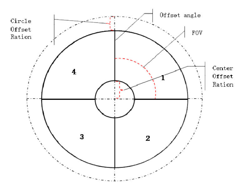
Each sector image in the figure below is corrected to a small rectangular split screen image. The calculation method for each small split screen image is similar. After calculating each small image, the corresponding coordinate arrays of each small image need to be concatenated into the coordinate array of the large image. For example, the coordinate calculation process of one small image is as follows. Input parameters include CenterOffsetRatio, CircleOffsetRatio, maxRadius, image width, and image height, which are the dimensions of each small output image, and the center point centerX and centerY of the input image. The output outputX and outputY are coordinates relative to the output small image.

1.2 Executing the Calibration Program#
Create an XML file containing the image paths, such as imx335-2592x1944-0.xml, and fill in the saved image paths from the previous step, in the form of:
<?xml version="1.0"?>
<opencv_storage>
<images>
images/imx335-2592x1944-0/0.png
...
</images>
</opencv_storage>
Edit run.bat, change the last parameter to the path of the XML file just created, and change the -o parameter to the path to save the output YAML file, then execute run.bat.
2. Using Dewarp with the VICAP Module#
VICAP controls distortion correction by loading the Dewarp configuration file. The Dewarp configuration file generated after compiling the K230 SDK is placed in <K230 SDK> src/big/mpp/userapps/src/sensor/config, and files with the .bin suffix are all dewarp configuration files. The first 8 bytes of their content are split screen parameters, and the rest are all mapping tables. VICAP loads the current sensor based on the file name.
Lens Correction Mode#
Note: Enabling Dewarp requires an additional vb pool, and the buf_size of the device properties should be changed to the sensor output buffer size. You can refer to the sample_vicap.c function sample_vicap_vb_init to initialize the vb pool.
The YAML file generated in the previous step needs to be placed in the <K230 SDK>/src/big/mpp/userapps/src/sensor/dewarp directory, and the K230 SDK should be compiled.
If the K230 SDK has been compiled before, you can avoid a full recompile. After placing the YAML file, directly run make mpp-apps. If you need to create an image, you also need to run make build-image.
Split Screen Mode#
The K230 SDK includes a built-in program for generating split screen mode configuration files. The source code is located in <K230 SDK>/src/big/mpp/userapps/src/sensor/dewarp/k230dwmapgen/exe/split_screen.c. After fully compiling the K230 SDK, a k230dwmapgen-splitscreen program will be generated in the <K230 SDK>/src/big/mpp/userapps/src/sensor/build directory. Running it will print the configuration file through standard output. If you need to keep it, you can redirect it to a file. This program defaults to the 1280x720 camera configuration split screen. If you need to modify parameters, you can change the parameters of the CreateUpdateWarpPolarMap function in its source code, recompile and run it.